
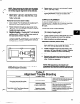
Technical data

I
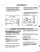
LEVEL’BASEPLATE
I_
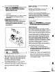
1.
Place 2 sets of wedges or shims on the foundation,
one set on each side of every foundation bolt.
The wedges should extend .75 in. (20mm) to
1.5 in. (40mm) above foundation, to allow for
adequate grouting. This will provide even support
for the baseplate once it is grouted.
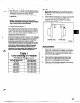
2. Remove water and/or debris from anchor bolt
\
holes/sleeves prior to grouting. If the sleeve type
bolts are being used, fill the sleeves with rags to
prevent grout from entering.
3. Carefully lower baseplate onto foundation bolts.
4. Level baseplate to within W (3.2mm) over length of
the baseplate and to within -088 in. (1.5mm) over
the width of the base by adjusting wedges.
5. Hand tighten bolts.
I
ALIGNMENT AND ALIGNMENT PROCEDURE
1
Before beginn&g any alignment procedure
make sure driver power is locked out. Failure
to lock out driver power will result in serious
physical injury.
To remove guard refer to coupling guard
assembly/disassembly instructions.
The points at which alignment is checked and
adjusted are:
l
Initial Alignment
is done prior to operation when
the pump and the driver are at ambient
temperature.
l
Final Alignment
is done after operation when the
pump and driver are at operating temperature.
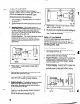
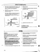
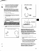
Alignment is achieved by adding or removing shims
from under the feet of the driver and shifting
equipment horizontally as needed.
NOTE: Proper alignment is the responsibility of
the installer and user of the unit.
Accurate alignment of the equipment must be
attained. Trouble free operation can be accomplished
by following these procedures.
ALIGNMENT CHECKS
Initial Alignment (Cold Alignment)
l
Before Grouting Baseplate - To ensure alignment
can be obtained.
l
After Grouting Baseplate - To ensure no changes
have occurred during grouting process.
l
After Connecting Piping - To ensure pipe strains
haven’t altered alignment. If changes have
occurred, alter piping to remove pipe strains on
pump flanges.
14