R-3A88 SERVICE MANUAL S3614R3A88PX/ MICROWAVE OVEN MODEL R-3A88 In interests of user-safety the oven should be restored to its original condition and only parts identical to those specified should be used. TABLE OF CONTENTS Page CAUTION, MICROWAVE RADIATION ................................................................................................................. 1 WARNING ............................................................................................................................
R-3A88
R-3A88 SERVICE MANUAL PRODUCT SPECIFICATIONS MICROWAVE OVEN R-3A88 GENERAL IMPORTANT INFORMATION APPEARANCE VIEW This Manual has been prepared to provide Sharp Corp. Service engineers with Operation and Service Information. It is recommended that service engineers carefully study the entire text of this manual, so they will be qualified to render satisfactory customer service.
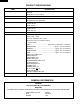
R-3A88 PRODUCT SPECIFICATIONS ITEM Power Requirements Power Consumption Power Output Case Dimensions Cooking Cavity Dimensions Turntable diameter Control Complement Set Weight DESCRIPTION 220 Volts 50 Hertz Single phase, 3 wire earthed 1.
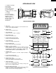
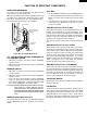
R-3A88 APPEARANCE VIEW 1. 2. 3. 4. 5. 6. Ventilation openings Oven lamp Door hinges Door safety latches See through door Door seals and sealing surfaces 7. Coupling 8. Door open button 9. Touch control panel 10.Digital readout 11.Wave guide cover 12.Power supply cord 13.Rating label 14.Earth wire 6 1 10 14 9 3 8 4 5 7 12 2 11 4 13 TOUCH CONTROL PANEL a HELP PAD Touch to select child lock, language or demonstration modes. Touch to get cooking information.
R-3A88 OPERATION SEQUENCE OFF CONDITION The circuits to the power transformer, fan motor and turntable motor are cut off when the 1st. latch switch and 2nd. interlock relay control switch are made open. The oven lamp remains on even if the oven door is opened after the cooking cycle has been interrupted, because the relay RY1 stays closed. Shown in the display is the remaining time. Closing the door activates all door interlock switches (1st. latch switch and 2nd. interlock relay control switch).
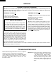
R-3A88 FUNCTION OF IMPORTANT COMPONENTS DOOR OPEN MECHANISM FUSE M8A The door is opened by pushing the open button on the control panel, refer to the Figure D-1. When the open button is pushed, the open button pushes up the switch lever, and then the switch lever pushes up the latch head. The latch heads are moved upward and released from latch hook. Now the door will open. 1. The fuse M8A blows when the contacts (COM-NO) of the 1st. latch switch and 2nd.
R-3A88 SERVICING WARNING TO SERVICE PERSONNEL Microwave ovens contain circuitry capable of producing very high voltage and current, contact with any part of the high voltage circuit will result in electrocution. High voltage capacitor, Power transformer, Magnetron, High voltage rectifier assembly, High voltage harness. REMEMBER TO CHECK 3D REMEMBER TO CHECK 4R 1) Disconnect the supply. 2) Door opened, and wedged open. 3) Discharge high voltage capacitor.
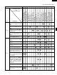
R-3A88 CK = Check / RE = Replace Home fuse blows when power supply cord is plugged into wall outlet. FUSE M8A blows when power supply cord is plugged into wall outlet. OFF CONDITION Display does not show anything when power supply cord is plugged into wall outlet. Display does not operate properly when STOP/CLEAR pad is touched. Oven lamp does not light at door opened. (Display appears.) Oven does not start when the START pad is touched. (Display appears) Oven lamp does not light (Display appears.
R-3A88 TEST PROCEDURES PROCEDURE LETTER A COMPONENT TEST MAGNETRON TEST NEVER TOUCH ANY PART IN THE CIRCUIT WITH YOUR HAND OR AN INSULATED TOOL WHILE THE OVEN IS IN OPERATION. CARRY OUT 3D CHECK. Isolate the magnetron from high voltage circuit by removing all leads connected to filament terminal. To test for an open circuit filament use an ohmmeter to make a continuity test between the magnetron filament terminals, the meter should show a reading of less than 1 ohm.
R-3A88 TEST PROCEDURES PROCEDURE LETTER COMPONENT TEST 6. Measure the final water temperature. (Example: The final temperature T2 = 21°C) 7. Calculate the microwave power output P in watts from above formula. Initial temperature .................................................................................................. T1 = 11°C Temperature after (49 + 2) = 51 sec. ..................................................................... T2 = 21°C Temperature difference Cold-Warm......................
R-3A88 TEST PROCEDURES (CONT'D) PROCEDURE LETTER COMPONENT TEST C B CARRY OUT 4R CHECKS. HIGH VOLTAGE RECTIFIER NOTE: FOR MEASUREMENT OF THE RESISTANCE OF THE RECTIFIER, THE BATTERIES OF THE MEASURING INSTRUMENT MUST HAVE A VOLTAGE AT LEAST 6 VOLTS, BECAUSE OTHERWISE AN INFINITE RESISTANCE MIGHT BE SHOWN IN BOTH DIRECTIONS. D HIGH VOLTAGE CAPACITOR TEST CARRY OUT 3D CHECKS. A. Isolate the high voltage capacitor from the circuit. B.
R-3A88 TEST PROCEDURES (CONT'D) PROCEDURE LETTER G COMPONENT TEST MONITOR RESISTOR TEST CARRY OUT 3D CHECKS. Disconnect the leads from the monitor resist. Using an ohmmeter and set on a low range. Check between the terminals of the monitor resistor. The resistance of monitor resistor is approx. 0.8 ohms. If incorrect readings are obtained, replace the monitor resistor. CARRY OUT 4R CHECKS. H MOTOR WINDING TEST CARRY OUT 3D CHECKS. Disconnect the leads from the motor.
R-3A88 TEST PROCEDURES (CONT'D) PROCEDURE LETTER COMPONENT TEST 2-2 In connection with indicators a) At a certain digit, all or some segments do not light up. b) At a certain digit, brightness is low. c) Only one indicator does not light. d) The corresponding segments of all digits do not light up; or they continue to light up. e) Wrong figure appears. f) A certain group of indicators do not light up. g) The figure of all digits flicker. 2-3 Other possible troubles caused by defective control unit.
R-3A88 TEST PROCEDURES (CONT'D) PROCEDURE LETTER COMPONENT TEST RELAY SYMBOL OPERATIONAL VOLTAGE CONNECTED COMPONENTS RY1 APPROX. 25.0V D.C. Oven lamp / Turntable motor / Cooling fan motor RY2 APPROX. 25.0V D.C. Power transformer CARRY OUT 4R CHECKS. N PROCEDURES TO BE TAKEN WHEN THE FOIL PATTERN ON THE PRINTED WIRING BOARD (PWB) IS OPEN To protect the electronic circuits, this model is provided with a fine foil pattern added to the primary on the PWB, this foil pattern acts as a fuse.
R-3A88 TOUCH CONTROL PANEL ASSEMBLY OUTLINE OF TOUCH CONTROL PANEL 7) Relay Circuit To drive the magnetron, fan motor, turntable motor and light the oven lamp. The touch control section consists of the following units as shown in the touch control panel circuit. (1) Key Unit (2) Control Unit 8) Indicator Circuit Indicator element is a Fluorescent Display. Basically, a Fluorescent Display is triode having a cathode, a grid and an anode.
R-3A88 DESCRIPTION OF LSI LSI(IZA683DR) The I/O signal of the LSI(IZA683DR) are detailed in the following table. Pin No. Signal I/O Description 1 Vdisp IN Anode (segment) of Fluorescent Display light-up voltage: -34V Vp voltage of power source circuit input. 2 R00 IN Signal coming from touch key. When either one of G12 line keys on key matrix is touched, a corresponding signal out of R10 - R13, R20, R21 and R22 will be input into R00. When no key is touched, the signal is held at "L" level.
R-3A88 Pin No. Signal I/O Description 25 BUZZ OUT Signal to sound buzzer. A: key touch sound (0.12 sec.). B: Completion sound (2.4 sec.). 26-27 D4-D5 OUT Segment data signal. Refer to the touch control panel circuit for the relationship between signals and indicators. Normally, one pulse is output in every synchronized signal period, and input to the anode of the fluorescent display. 28 D6 OUT Segment data signal. Signal similar to P41. Key strobe signal. Signal applied to touch-key section.
R-3A88 SERVICING 1. Precautions for Handling Electronic Components This unit uses CMOS LSI in the integral part of the circuits. When handling these parts, the following precautions should be strictly followed. CMOS LSI have extremely high impedance at its input and output terminals. For this reason, it is easily influenced by the surrounding high voltage power source, static electricity charge in clothes, etc. and sometimes it is not fully protected by the built-in protection circuit.
R-3A88 COMPONENT REPLACEMENT AND ADJUSTMENT PROCEDURE WARNING: Avoid possible exposure to microwave energy. Please follow the instructions below before operating the oven. 1. Disconnect oven from power supply. 2. Make sure that a definite” click” can be heard when the microwave oven door is unlatched. (Hold the door in a closed position with one hand, then push the door open button with the other, this causes the latch leads to rise, it is then possible to hear a “click’ as the door switches operate.) 3.
R-3A88 plate right. 4. Remove transformer from bottom plate right. 5. Remove the one (1) terminal insulator from filament lead (longer one) of power transformer. Re-install 1. Insert tube into filament lead (longer one) of power transformer. 2. Install the terminal insulator to receptacle of filament lead (longer one) of power transformer. 3. Rest transformer on the bottom plate right with its primary terminals toward the oven face plate. 4. Secure transformer with four screws to bottom plate right. 5.
R-3A88 TURNTABLE MOTOR REMOVAL 6. Remove two (2) screws holding turntable motor to oven cavity. 7. Now the turntable motor is free. 8. After replacement use the one (1) screw to fit the turntable motor cover. NOTE: The one (1) screw to fit the turntable motor cover should be XOTSD40P12000, XOTSD40P10000 or XOTSD40P08000. 1. Disconnect oven from power supply. 2. Remove turntable and turntable support from oven cavity. 3. Lay the oven on it's backside.
R-3A88 OVEN LAMP AND LAMP SOCKET REMOVAL Oven lamp socket 1. CARRY OUT 3D CHECKS. 2. Pull the wire leads from the oven lamp socket by pushing the terminal hole of the oven lamp socket with the small flat type screw driver. 3. Bend the tab of the oven cavity holding the lamp socket. 4. Lift up the oven lamp socket. 5. Now, the oven lamp socket is free. Terminal Wire lead Terminal hole Flate type small screw driver Figure C-3. Oven lamp socket POWER SUPPLY CORD REPLACEMENT Removal 5.
R-3A88 3. Monitor switch contacts close when door is opened. 4. Re-install outer case and check for microwave leakage around door with an approved microwave survey meter. (Refer to Microwave Measurement Procedure.) should be less than 0.5mm. The vertical position of the latch hook should be adjusted so that the 1st. latch switch 2nd. interlock relay control switch are activated with the door closed.
R-3A88 SEALER FILM Note: After any service to the door; (A) Make sure that door sensing switch and secondary interlock switch are operating properly. (Refer to chapter "Test Procedures".). (B) An approved microwave survey meter should be used to assure compliance with proper microwave radiation emission limitation standards. Installation 1. Put the adhesive tape on the backing film of the sealer film as shown in Fig. C-8. 2. Tear the backing film by pulling the adhesive tape. 3.
R-3A88 MICROWAVE MEASUREMENT After adjustment of door latch switches, monitor switch and door are completed individually or collectively, the following leakage test must be performed with a survey instrument and it must be confirmed that the result meets the requirements of the performance standard for microwave oven. 2. 3. REQUIREMENT The safety switch must prevent microwave radiation emission in excess of 5mW/cm2 at any point 5cm or more from external surface of the oven.
BLU 2ND. INTERLOCK RELAY CONTROL SWITCH THERMAL CUT-OUT 95˚C (FAN) 25 1ST. LATCH SWITCH Figure O-2. Oven Schematic-Cooking Condition MAGNETRON POWER TRANSFORMER MONITOR RESISTOR 0.8/20W N.O. H.V. RECTIFIER TTM FM TTM FM OL CONTROL UNIT H.V. RECTIFIER CAPACITOR 1.07µ AC2100V MONITOR SWITCH TURNTABLE MOTOR FAN MOTOR OVEN LAMP B2 B1 A3 A5 A1 MAGNETRON POWER TRANSFORMER MONITOR RESISTOR 0.8/20W RY-1 RY-2 THERMAL CUT-OUT 145˚C (OVEN) THERMAL CUT-OUT 145˚(MG) FUSE M8A 2ND.
1 2 3 26 RY2 CN-A 5 1 CN-B 2 1 RY1 5 4 3 GRY 2 1 ORG CN-A 2 GRN 1 GRY CN-B G RED CN-G LSI N.C. COM. GRY 4 NO 5 GRY GRY MONITOR RESISTOR TURNTABLE MOTOR BLK ORG GRY RED RED WHT RED WHT BRN FUSE M8A LIVE BRN BLU NEUTRAL HIGH VOLTAGE TRANSFORMER G / Y EARTH POWER SUPPLY CORD HIGH VOLTAGE CAPACITOR HIGH VOLTAGE WIRE B MAGNETRON HIGH VOLTAGE COMPONENTS RED WHT 5 D Figure S-1.
3 27 4 B1 B2 NO VRS1 b Note : c d RY2 RY1 2 4 Q22 DTA143ES (J5) (J3) - + R11 56K C30 (J6) (J4) R31 4.7K - + 5 IF NOT SPECIFIED, 0.
R-3A88 1 2 4 3 5 6 QKITPB014MRE0 A A FLR.
R-3A88 PARTS LIST Note: The parts marked "∆" may cause undue microwave exposure. The parts marked "*" are used in voltage more than 250V. REF. NO. PART NO. DESCRIPTION 1- 1 1- 2 1- 3 1- 4 1- 5 1- 6 1- 7 1- 8 1- 9 1-10 1-11 1-12 1-13 1-14 1-15 1-16 1-17 QSW-MA110WRE0 QSW-MA111WRE0 RV-MZA197WRE0 RTHM-A080WRE0 FH-DZA047WRK0 RC-QZA172WRE0 RMOTEA265WRE0 RTHM-A072WRE0 QACC-A065WRE0 QFS-CA010WRE0 QFSHDA019WRE0 QSOCLA022WRE0 RLMPTA069WRE0 RMOTDA169WRE0 RR-WZA003WRE0 RTRN-A480WRE0 QPLGAA018WRE0 1st.
R-3A88 Note: The parts marked "∆" may cause undue microwave exposure. The parts marked "*" are used in voltage more than 250V. REF. NO. (J35) RY1 RY2 SP40 T1 VRS1 ZD2 3- 2 3- 2-1 3- 3 3- 4 3- 5 PART NO.
R-3A88 HOW TO ORDER REPLACEMENT PARTS To have your order filled prompty and correctly, please furnish the following information. 1. MODEL NUMBER 3. PART NO. 2. REF. NO. 4.
R-3A88 2 1 4 3 6 5 7-5 OVEN AND CABINET PARTS 7-5 6-2 2-1 A A 7-5 1-13 1-12 6-1 4-13 7-5 B B 1-4 4-12 7-1 6-8 4-11 C C 7-6 1-3 6-10 7-6 6-15 7-6 D 4-19 4-5 D 7-6 6-14 7-3 A 1-17 1-9 E E 4-8 4-10 7-5 1-5 1-1 7-1 4-9 7-2 1-4 7-5 4-14 1-6 7-1 4-18 1-2 F 4-1 2-3 1-14 7-1 4-6 4-2 4-3 4-15 6-11 7-4 7-1 x2 F 7-6 1-1 4-7 7-3 4-4 1-10 7-6 1-16 G 4-17 7-3 1-15 2-4 7-8 7-7 1-9 7-5 G 1-11 A 7-1 1-7 4-16 1-8 7-2 2-2 7-5 H H 2-4 7-6 1 2 7-5 4
R-3A88 2 1 4 3 6 5 3- 2 A CONTROL PANEL PARTS A 3- 1 3- 5 B B 3-2-1 DOOR PARTS C C 5-3 3- 3 5-2 3- 4 D D 5-1 5-4 E E 5-6 F F 5-7 5-5 MISCELLANEOUS 6-5 G G 6-4 Actual wire harness may be different from illustration.
R-3A88 '96SHARP CORP. (3U0.