
Specifications


4-6 P/N 13999-002 Info Manual
Section 4 Cirrus Design
Normal Procedures SR20
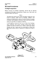
Preflight Walk-Around
1. Cabin
a. Required Documents................................................ On Board
b. Avionics Power Switch.......................................................OFF
c. Bat 2 Master Switch ........................................................... ON
d. Avionics Cooling Fan .................................................... Audible
e. Voltmeter ................................................................ 23-25 Volts
f. Flap Position Light ........................................................... OUT
g. Bat 1 Master Switch............................................................ ON
h. Lights ............................................................. Check Operation
i. Stall Warning .................................................................... Test
• Note •
Test stall warning system by applying suction to the stall
warning system inlet and noting the warning horn sounds.
j. Fuel Quantity .................................................................Check
k. Fuel Selector ..............................................Select Fullest Tank
l. Flaps.................................................... 100%, Check Light ON
m. Oil Annunciator .................................................................... On
n. Bat 1 and 2 Master Switches.............................................OFF
o. Alternate Static Source............................................. NORMAL
p. Circuit Breakers .................................................................... IN
q. Fire Extinguisher ..................................Charged and Available
r. Emergency Egress Hammer ......................................Available
s. CAPS Handle .................................................... Pin Removed
2. Left Fuselage
a. Door Lock ...................................................................... Unlock
b. COM 1 Antenna (top) ..................... Condition and Attachment
c. Wing/Fuselage Fairing....................................................Check
d. COM 2 Antenna (underside)........... Condition and Attachment
September 2011