
Instruction manual


1-30 12. Modular Jack (MJ1/MJ2)
ZM-71SE Setting
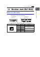
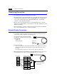
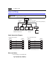
1. The use of modular jacks 1 and 2 can be set on the ZM-71SE editor.
2. Select [Modular] from the [System Setting] menu. The [Modular Jack] dialog is
displayed. Select the use of modular jacks 1 and 2 from the following options.
*1 Refer to the next section “Transferring Screen Data.”
*2 Select this option when connecting the card recorder (ZM-1REC).
*3 Refer to the next section “Barcode Reader Connection.”
*4 Select this option when connecting the serial extension I/O (ZM-322ME).
*5 Select this open when “Multi-link 2” is selected for [Connection] and “1” is set for [Local Port]
on the [Comm. Parameter] dialog.
*6 Select this option when connecting the PLC2Way.
*7 Select this option for ZM-Link connection.
*8 Refer to “ZM-302EU (RGB input + sound output unit User’s Manual).”
*9 Select [Ladder Tool] when using the ladder transfer function with MITSUBISHI’s QnHCPU
port (Q mode) selected for the PLC type.
*10 Select this option for Modbus slave connection.
*11 Select this option when connecting the printer with serial interface. Refer to page 1-37.
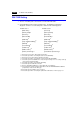
Modular Jack 1 Modular Jack 2
[Editor Port]
*1
[Not used]
[Memory Card]
*2
[Memory Card]
*2
[Barcode]
*3
[Barcode]
*3
[External-I/O]
*4
[External-I/O]
*4
[Multi-Link]
*5
[Multi-Link]
*5
[Temp. CTRL/PLC2Way]
*6
[Temp. CTRL/PLC2Way]
*6
[ZM-Link]
*7
[ZM-Link]
*7
[Touch Switch]
*8
[Touch Switch]
*8
[Ladder Tool]
*9
[Ladder Tool]
*9
[Modbus Slave]
*10
[Modbus Slave]
*10
[Printer (Serial Port)]
*11
[Serial Printer (Serial Port)]
*11