
Instruction manual


1
7. Mounting Procedure 1-19
Hardware Specifications
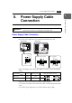
7. Mounting Procedure
Mounting Procedure
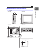
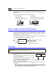
1. Cut out the mounting panel (max. thick: 5 mm) to match the dimensions shown below.
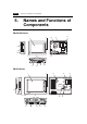
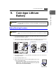
2. Insert four fixtures attached to the ZM-300 series into the mounting holes, and tighten
them with the locking screws.
Tightening torque
ZM-350/360/370: 0.3 to 0.5 N•m
ZM-380: 0.5 to 0.7 N•m
* When the ZM-300 unit is attached to the
mounting panel, the fixtures and frame
grounds (FG) are connected. To prevent
static electricity, be sure to connect the
mounting panel to the frame ground.
3. Mount the gasket in contact with the mounting panel so that it will be sandwiched
securely between the unit and the mounting plate.
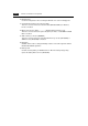
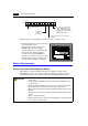
Mounting Angle
Install the unit within the angle of 15° to 135° degrees as
shown on the right.
• When the mounting angle is between 15° and 45° or
when you use the option module, ZM-301EU (video input
and audio output), adjust the ambient temperature
between 0°C and +40°C.
165.5
220.5
+0.5
−0
−0
+
0.5
246.2
313
ZM-380
ZM-350/360
216.2
289
+0.5
−0
−0
+
0.5
ZM-370
+0.5
−0
−0
+
0.5
F1
F2
F3
F4
F5
F6
F7
SYSTEM
POWER
216.2
289
+0.5
−
0
−
0
+
0.5
Mounting panel
Panel cut-out hole
• Panel cut-out dimensions
(Unit: mm)
MJ1
MJ2
PRINTER
CF
CN5
MEMORY
CN6
LAN
CN1
100-240VAC
L N
Fixtures
Mounting hole
Mounting hole
ZM-300 series
Mounting panel
Fixtures
17.8
10.5
30.0
Fixture dimensions
(Unit: mm)
15°
135°
90°
0°
D
i
s
p
l
a
y
D
i
s
p
l
a
y