
Instruction manual
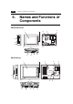


1-18 6. Names and Functions of Components
10. Mounting holes
Used for inserting fixtures when securing the ZM-300 series to the mounting panel.
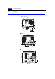
11. Communication interface unit connector (CN5)
This is the connector where the network module (ZM-80NU/80NU2) for Ethernet,
FL-net is mounted.
12. Option unit connector (CN6).....................ZM-300 (high-performance) only
This is the connector where the option unit (EU-xx) for video, sound, RGB IN or RGB
OUT is mounted.
13. Add-on memory connector (MEMORY)
This is the connector where the optional FLASH memory cassette (ZM-300EM) or
SRAM cassette (ZM-300SM) is mounted.
14. DIP switch
8-bit DIP switch used for setting terminating resistance of the CN1 signal line and the
MJ1/MJ2 RS-422/485 signal line.
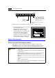
15. Battery holder
Contains a backup battery for SRAM and clock. When the battery voltage drops,
replace the battery with a new one (ZM-300BT).