
Instruction manual


5
2. MITSUBISHI PLC 5-23
Connection to PLCs
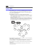
• To have access to the PLC in the other network on NET/10, specify the network number
in the OPEN macro for the screen on the ZM-71SE editor. This macro command
should be [OUT_ENQ] of system call [SYS]. It is not possible to have access to the
CPU on the different network from the same screen.
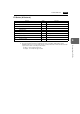
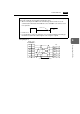
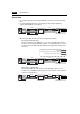
• Network specifying macro[OUT_ENQ] of system call [SYS]
F1 memory
“n + 0” and “n + 1” are fixed to “0” and “2,” respectively.
“n + 2” (system code) should be: 1: NET/10 2: NET II (/B)
For “n + 3” (network number), set “0” when NET II (/B) is selected for “n + 2” (system
code) or the network number to be accessed when NET/10 is selected.
Do not use this macro for any purpose other than OPEN macro for a screen. Doing so
triggers network switching at the time of macro execution, resulting in a communication
error.
Refer to the explanation on network registration contained in the operation manual for
MITSUBISHI’s Standard Link/Multi-drop Link Unit.
• For the NET II (/B) data link system and NET/10 network system, refer to
MITSUBISHI’s manual.
Available Memory
For the available memory of the PLC to be accessed, refer to “Available Memory” page
5-15. Note that the CPU number must be set on the ZM-71SE editor.
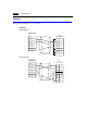
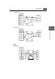
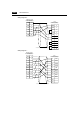
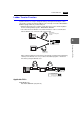
Wiring
Refer to the wiring diagram with the standard type link unit.
n+0 Always 0
n+1 Network selection: 2
n + 2 System code
n + 3 Network number