
Instruction manual
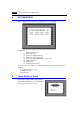


3
1. 1 : 1 Connection 3-3
Serial Communications
RS-422/485 Connection
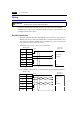
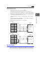
• Connect twist-pair cables between +SD/−SD and +RD/−RD.
• If the PLC has the terminal for signal ground (SG), be sure to connect a wire.
• Connect the shielded cable either to the ZM-300 series or PLC side. This connection
diagram shows the case where the shielded cable is connected on the ZM-300 series
side. When connecting the shielded cable to the ZM-300 series side, connect it to pin 1
of the connector or the connector case cover.
• To use a terminal block for connection, use Sharp Corporations’ “ZM-1TC” optionally
available.
• For the terminating resistance on the ZM-300 series, turn the DIP switch (DIPSW7) to
the ON position on the side towards the rear.
• Twist-pair cables of 0.3 mm sq. or above are recommended.
4-wire system:
2-wire system:
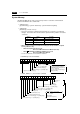
ZM-71SE Setting
For serial communications, the following settings on the ZM-71SE editor are required. The
settings in the [Select PLC Type] and [Comm. Parameter] dialogs are shown on the Main
Menu screen of the ZM-300 series. (Refer to “Chapter 2 LCD Control Terminal Operations.”)
FG
+RD
−RD
+SD
−SD
1
24
25
12
13
SG 7
ZM-300 (CN1)
Signal Name Pin No.
Shield
To the PLC’s
RS422 port
Receive data (+)
Send data (+)
SG
Receive data (−)
Send data (−)
FG
+RD
−RD
+SD
−SD
1
24
25
12
13
SG 7
ZM-300 (CN1)
Signal Name Pin No.
Shield
To the PLC’s
RS422 port
Send/receive data (+)
SG
Send/receive data (−)