
Technical data
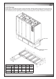
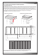
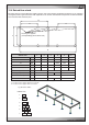

/08.2011/air/7
150
120
BC
FC
A
890
ED
20
25
25
Baugröße 1 2 3 4 5 7
A mm 950 1400 1750 2200 2550 3110
B mm 190 287 237 237 275 187
C mm 650 1000 1400 1800 2000 1200/1300
D mm 147 107 107 107 107 198
E mm 650 650 675 675 675 675
F mm - - - - - 1797
T mm 890 890 890 890 890 980
T
EN
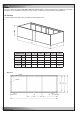
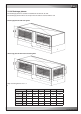
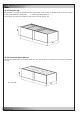
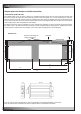
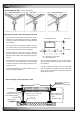
12.3.7 Adapter plate with damper or flexible connection
- Connection on the unit
The adapter plate serves to attach a damper or a flexible connection on top of the unit or a duct. First install the actu-
ator onto the louver shaft on the right side looking at the unit front. Then fix the louver with the actuator on the adapter
plate. Now mount the adapter plate with pre-mounted louver on the unit top by means of a screw connection.
The damper actuator, which is controlled via a 24 V signal by the controller, has to be electrically connected. For this
the cable, which is already connected at the motor, must be routed through an opening in the adapter plate into the
unit and then be connected at the controller in the electric box according to the electric diagram.
In downflow units route the cable through the side panel.
Adapter plate with damper Adapter plate with flexible connection
Cabinet size
If the air side has to be continued by a duct, the installation of a flexible connection is necessary.
Take into account the installation of pressure compensations in the flexible connection.
*Version with flexible duct connection