
Technical data

/08.2011/18/22
U
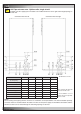
ASU ... CW 320/420 550/650 800/950 1000/1180 1250/1550
Ø Kaltwasserleitung,
bauseits [mm]
35 42 54 64 64
Außengewinde [Zoll]
1 1/4" 1 1/2" 2" 2" 2"
Wassereintritt
L4 L4 L10 L10 L10
Wasseraustritt
L1 L1 L9 L9 L9
Kondensatablauf
L8 L8 R4 R4 R4
Elektro-Einspeisung R2 R2 R2 R2 R2
PWW-Eintritt
R4 R4 -* -* -*
PWW-Austritt
R5 R5 -* -* -*
Befeuchterzu-/ablauf
R8 R8 R8 R8 R8
EN
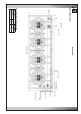
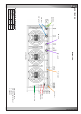
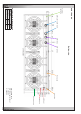
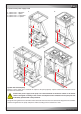
6.2.3 Pipe entrance area - Upflow units, single circuit
At Upflow units the supply pipes and cables are introduced from the left or right side through openings in
the side wall.
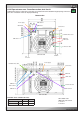
Connection from the left Connection from the right
All dimensions in mm.
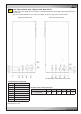
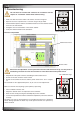
The openings R1, R9 and
R10 can not be used.
* the installation of a hot
water reheat is not possible
in these units.
ASU ... CW
Ø Chilled water line,
by client [mm]
external thread [inch]
Water inlet
Water outlet
Condensate drain
Power supply
HWR inlet
HWR outlet
Humidifier inlet/outlet
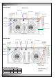
Notes:
For the routing of the piping into the unit there are sometimes several possibilities. The most favourable openings
are those which are recommended in the tables. The lines for the power supply, the humidifier connections and the
condensate drain can be routed through the remaining openings as desired.