
Service manual


ELI 250/210__________________________________________________________________________
6-6
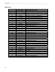
Description of printout
At the top of the writer test print out will be the printable characters of the writer.
The next section will have a 200-mm line. This line should be measures with a ruler and will indicate if there is a
writer motor problem if the line is too short or too long. The tolerance of this line is +/- 2-mm.
The next line that prints is a zigzag line. Check to see that none of the dots are missing.
The next line that prints is an indication of the cue sensor. At the beginning of the printout there should be a dip
towards the bottom off the page and then it should move to a baseline level. Note: there will be fluctuation in this
line, this is normal. Look for extreme variations that can indicate possible problems with the cue sensor or cue
sensor circuitry.
There will then be two additional lines of zigzag printed. Check to see that none of the dots are missing.
At the bottom of the page, starting in the lower left and continuing to the top of the page, two diagonal lines will be
printed. Check these lines for any missing dots. If dots are missing the print head may need to be cleaned or
replaced. Also check the lines for any “steps” which can indicate a motor problem.
Another item that is printed is a circle. Check the circle to make sure that there are no breaks or gaps in the printing.
This can indicate a problem with the writer motor and the thermal printhead.
When printing an ECG at different paper speeds the calibration pulse printed at the beginning of each trace can be
used to check the paper speed. Check the calibration pulse by measuring the width and amplitude of the pulse at the
beginning of each line of ECG tracing. Use the following table for the correct measurements.
Note: The measurements should be made using a ruler and not the grid on the paper.
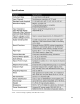
Paper Speed
Cal Pulse Width
5mm/sec 1mm
10mm/sec 2mm
25mm/sec 5mm
50mm/sec 10mm
Gain Setting
Cal Pulse Amplitude
5mm/mV 5mm
10mm/mV 10mm
20mm/mV 20mm
Adjusting the Writer Cue Sensor
Note: This test should be performed with the AC power turned on.
1) Install paper into the unit with the cue mark approx. 1 – 2 inches away from the tear bar. Make sure that the cue
sensor is seeing white and not any markings on the paper.
2) Use a DMM to measure the DC voltage at test point P15 on the motherboard with respect to ground (P12).
Adjust R323 on the motherboard to between 1.95 V-DC and 2.05 V-DC at test point P15. Set this as close to 2.0
V-DC as possible.
3) Perform either the Writer test or print a test ECG. The paper should cue to the next sheet of paper, print and then
advance to the beginning of the next sheet of paper.
4) If the Writer test is performed the results should be compared with the test printout in this manual.