
Service manual


____________________________________________________________________________Section 5
5-3
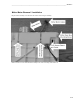
Main System Board
The main system board or motherboard of the ELI 250/210 contains the digital logic circuitry and the power supply
of the ELI 250/210. The rear section of the motherboard (located at what is the back of the unit when mounted in
the chassis) contains the power supply of the unit.
Power Supply
The AC power supply consists of the AC inlet connector, AC inlet fuses and a switching power supply. The
switching power supply automatically senses the input voltage coming in on the AC line and switches to supply the
proper voltage to the unit.
The AC power supply powers the unit for operation and charges the internal battery. When the unit is not connected
to an AC power source the internal battery will supply power to operate the unit.
Logic Circuitry
The logic circuitry or digital section of the mother board contains the microprocessor, FLASH memory, Real time
clock, LCD & keyboard control circuitry, interface circuitry for modem and RS232 communications, and the Writer
interface circuitry.
Writer Interface
The writer interface on the motherboard consists of 5 connectors. Two of the connectors/cables connect directly to
the thermal printhead of the writer. These two cables carry power, data and ground connections to the printhead.
The third cable of the writer interface is for motor control and carries power, ground and stepper signals to the
writer motor. The fourth cable is for the cue sensor and allows the motherboard to sensor when the paper is at the
correct position to start printing. The fifth cable is an additional grounding wire for the printhead.
Accessories/Options
The motherboard has two PCMCIA slots on it for additional options to the unit. The lower PCMCIA slot is reserved
for the optional modem and the upper slot is open for future options.
The ELI 250/210 also has a 9-pin RS232 port. This port serves two functions. The first is it allows software to be
downloaded to the unit and the second, and most common, is for transmitting ECG’s either to another unit or to a
data management system.
Keyboard and LCD interface
The keyboard and LCD interface consists of a large ribbon cable that connects from the motherboard to the
keyboard and LCD of the unit. This cable carries the data to the LCD and keyboard inputs to the motherboard.
Front End Board
The analog information from the patient enters the unit via the patient cable then enters the front end board. The
information is immediately digitized to create the 12 leads of ECG data. This digitized information is then sent to
the motherboard via an interconnect cable. This interconnect cable carries power and ground from the motherboard
to the front end and also caries serial clock and data from the front end to the motherboard. If the motherboard does
not receive the clock and data signals from the front end, the LCD will not display any ECG waveforms.