
Instruction manual


47
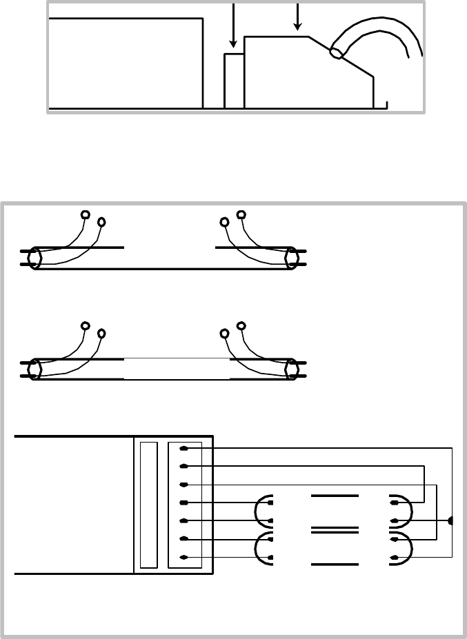
1. The test adapter is inserted behind the release lever of the 45°-
plug-in terminals or, in the case of combi-wiring terminals, in the
respective non-wired IDC or horizontal plug-in contact.
2. Instead of the lamps the two dummy lamps are inserted in the
lampholders of the empty luminaire.
3. Measure the resistance between A and B and between C and D.
The resistance between A and B and between C and D should be
100 Ω.
4. Measure the resistance between E and F and between G and H in
the same way.
If the measured resistance is not 100 Ω, the wiring is incorrect.
Dumm
y
1
Dumm
y
2
Ada
p
ter
A
B
C
D
E
F
G
H