
Instruction manual


45
significant change in temperature for some time). The supply voltage
should be held constant at least throughout the entire measuring cycle at
the rated voltage of the lamp.
The
following procedure is recommended for the thermal analysis of the
luminaire, taking into account the design requirements specified in EN
60598-1:
1. Thermal situation in the luminaire without contol gear heat.
Luminaire in measurement setup according to EN 60598-1 in
standard mounting position, equipped with ECG and lamp and fitted
with thermocouples. The lamp is supplied from external control
gear, and not from the built-in ballast. In this way the temperature
rise in the entire set-up resulting only from the lamp can be
measured and the thermal “link” to the environment can be
optimized.
2.
Thermal situation in the luminaire with contol gear heat.
Arrangement as described in 1., but the lamp is supplied from
internal control gear. By comparison with the measured values
obtained already, the additional heat generated by the ECG can
now be assessed.
3.10 Luminaire Wiring Test
for Two-lamp
Luminaires
3.10.1 Testing with a Test
Adapter and Dummy
Lamps
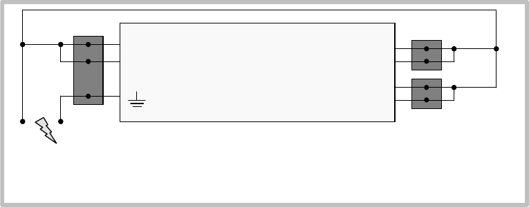
A more precise wiring test for two-lamp luminaries than the one described
in Section 3.10.1 can be performed with a test adapter (own design with
the resistors shown in the diagram) and a sample tube (dummy lamp with
sockets measuring the resistance). This test can be used for two-lamp
luminaires equipped with the before mentioned ECGs.
¾Insulation test: 500 VDC acc. to EN 60598 app. 3...5 sec.; R = 2MΩ
¾High voltage test (100% for each luminaire)
N
L
1
2
3
4
QUICKTRONIC
®
lamp terminal
output
socket 1
output
socket 2
Earth connection via ECG- housing
¾Insulation test: 500 VDC acc. to EN 60598 app. 3...5 sec.; R = 2MΩ
¾High voltage test (100% for each luminaire)
N
L
1
2
3
4
QUICKTRONIC
®
lamp terminal
output
socket 1
output
socket 2
Earth connection via ECG- housing