
Operating instructions


34
Models C709 & C717Operating Procedures
Model C717 Freezer Door Assembly (Cont'd .)
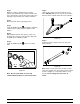
Step 8
Slide the pivot pin through the draw handles as the
handles are inserted into the draw valves.
Figure 75
Note: This freezer features adjustable draw handles
to provide portion control, giving a better consistent
quality to your product and controlling costs. The
draw handles should be adjusted to provide a flow
rate of 5 to 7-1/2 oz. (142 g. to 213 g.) of product by
weight per 10 seconds.
To INCREASE the flow rate, turn the adjustment
screw CLOCKWISE. To DECREASE the flow rate,
turn the adjustment screw COUNTER-
CLOCKWISE.
Step 9
Snap the design caps over the bottom of the door
spouts.
Step 10
Slide the two rear drip trays into the holes in the
back panel. Slide the two drip pans into the holes in
the side panels. (See Figure 76.)
Figure 76
Step 11
Install the front drip tray and splash shield under the
door spouts. (See Figure 77.)
Figure 77
Feed Tube Assembly
Step 1
Slide the three o-rings into the grooves of the inner
feed tube.
Figure 78