
Operation Manual


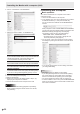


Table Of Contents
- IMPORTANT INFORMATION
- DEAR SHARP CUSTOMER
- SAFETY PRECAUTIONS
- TIPS AND SAFETY INSTRUCTIONS
- MOUNTING PRECAUTIONS
- Supplied Components
- System Requirements
- Part Names
- Connecting Peripheral Equipment
- Connecting the Power Cord
- Binding Cables
- Preparing the Remote Control Unit
- Removing the Handles
- Mounting a web camera
- Turning Power On/Off
- Touch Panel / Touch Pen Preparations
- Touch action
- Basic Operation
- Menu Items
- Initialization (Reset)/Functional Restriction Setting (FUNCTION)
- Controlling the Monitor with a computer (RS-232C)
- Controlling the Monitor with a computer (LAN)
- Troubleshooting
- Specifications
- Mounting Precautions (For SHARP dealers and service engineers)

53
E
Controlling the Monitor with a computer (RS-232C)
Initialization/Functional Restriction Setting (FUNCTION) menu
Function
Command Direction
Parameter Reply Control/Response contents *
ALL RESET RSET W 0-1 0: ALL RESET 1, 1: ALL RESET 2 -
ADJUSTMENT LOCK ALCK WR 0-2 0-2 0: OFF, 1:ON 1, 2:ON 2
●
ADJUSTMENT LOCK TARGET ALTG WR 0-2 0-2 0: REMOTE CONTROL, 1: MONITOR BUTTONS, 2: BOTH
○
OSD DISPLAY LOSD WR 0-2 0-2 0: ON 1, 1: OFF, 2: ON 2
LED OFLD WR 0-1 0-1 0: ON, 1: OFF
TEMPERATURE ALERT TALT WR 0-2 0-2 0: OFF, 1: OSD & LED, 2: LED
STATUS ALERT SALT WR 0-2 0-2 0: OFF, 1: OSD & LED, 2: LED
POWER BUTTON PBTN WR 0-1 0-1 0: MONITOR, 1: EXT. CONTROLLER
EXTERNAL CONTROLLER INPUT PCIP WR 0-3, 5, 6 0-3, 5, 6 0: D-SUB, 1: DisplayPort1, 2: HDMI1, 3: HDMI2, 5: HDMI3, 6: DisplayPort2
(“ERR” when MONITOR is selected for POWER BUTTON.)
SIGNAL RESPONSE LEVEL HDUC WR 1-200 1-200
Others
Function
Command Direction
Parameter Reply Control/Response contents *
SIZE (Screen size selection) WIDE WR 1-5 1-5
1: WIDE, 2: NORMAL, 3: Dot by Dot, 4: ZOOM1, 5: ZOOM2
○
INFORMATION Model INF1 R Value
●
Serial no. SRNO R Value
Temperature sensor DSTA R 0 Internal temperature normal
1 Internal temperature abnormal has occurred and the monitor is in standby mode
2 Internal temperature abnormal occurred (To delete the information of temperature
abnormal, turn off the main power.)
3 Internal temperature abnormal has occurred and backlight brightness is dimmed
4 Temperature sensor abnormal
Temperature acquisition ERRT R Value Returns the temperature at the temperature sensors.
Indicates a temperature sensor abnormality when “126” is returned.
○
Cause of last standby mode STCA W 0 Initialization
●
R 0 No detectable error has occurred
1 Standby mode by POWER button or MONITOR OFF button
2 Main power off by the main power switch
3 Standby mode by RS-232C or LAN
4 Input signal waiting mode by No Signal
6 Standby mode by abnormal temperature
8 Standby mode by SCHEDULE setting
9 Standby mode by DDC/CI
10 Standby mode by HDMI CEC
20 Standby mode by OFF IF NO OPERATION setting
Touch operation valid/invalid TPEN WR 0-1 0-1 0: Invalid, 1: Valid
“ERR” when TOUCH INPUT SELECT is set to INVALID or the touch panel is not
connected.
-
FREEZE FRMD WR 0-1 0-1 0: FREEZE release, 1: FREEZE execute
Commands for setting of the GAMMA user data
Function
Command Direction
Parameter Reply Control/Response contents *
Red gamma data transfer UGRW W aaxxxx
···
xxxxcc
(xxxx: 32 pieces)
aa: 01-16
xxxx: 0000-1023
cc: 00-FF
aa: Block number
xxxx: 32 pieces of user data
cc: Checksum (ASCII data) of the block number and user data
○
Green gamma data transfer UGGW W
Blue gamma data transfer UGBW W
Red gamma data read UGRR W 1-16 xxxx
···
xxxx
(xxxx: 32 pieces)
xxxx: 0000-1023
xxxx: User data of 32 pieces
Green gamma data read UGGR W 1-16
Blue gamma data read UGBR W 1-16
User data initialize UGRS W 0 Initialize the user data.
User data save UGSV W 0 Save the user data in the monitor.