
Installation Manual/Installationsanleitung


8
7.2 Clamp mounting for PV modules
7.2.1 Arranging the clamps
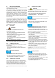
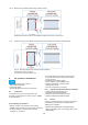
■ Permissible arrangement
Fig. 5 Permissible clamp arrangement for framed
modules
a : Symmetrical clamping on the long sides
b : Asymetrical clamping on the long sides
c : Symentrical clamping on the short sides
d : Asymetrical clamping on the short sides
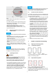
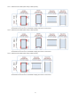
■ Impermissible alignment
Fig. 6 Impermissible clamp arrangements (1)
a: Missing clamps, b, c: Clamping on both short and
long sides.
Fig. 7 Impermissible clamp arrangements (2)
d: Protruding clamps, e: Opposing clamps have
different distances to the PV module corners,
f: Asymmetrical clamps on the short sides.
7.2.2 Clamp dimensions
Observe the following information for clamp lengths
and depths.
■ Clamp lengths and depths
Fig. 8 Definition of clamp length and depth for
framed PV modules
a: Clamp length, b: Clamp depth.
• The required minimum length of a clamp (parallel to
the frame side) is 50 mm.
• The required minimum depth of a clamp (perpendicu-
lar to the frame side) is 7 mm.
• Depending on the ambient conditions (e.g. angle,
suction load or tolerances of the substructure) a
higher minimum area per clamp may be required.
• The clamps determine the actual clamp depth and
length.
• Observe the instructions of the clamp manufacturer.
7.2.3 Tightening torque for clamp mounting
Tighten the screws on the clamp manually. If you use
an automatic screwdriver, then set a suitable maximum
tightening torque. You can find details for this in the
manufacturer‘s documentation for the substructure.
7.3 Screw mounting
The PV modules have a mounting hole with a diameter
of 9 mm.
For M8 stainless steel screws, use a maximum torque
of 24 Nm.
This applies to unlubricated screws with standard thread and strength
class of 8.8 (minimum breaking load 29.2 kN).
7.4 Insertion mounting
Observe the manufacturer‘s instructions for the mount-
ing system. Use the earthing holes for the potential
equalisation.
Although edge-to-edge mounting is possible (see also
Ch. 5.4.1: „Intervals between PV modules with stand-
ard frames“), we recommend mounting at intervals.
7.5 Load levels
A load can be a pressure load as well as a suction
load. Loads from snow and wind need to be taken into
account at the installation site.
The maximum permissible load is 2400Pa (for wind
and snow) when mounting the modules by using
screws, clamps or insertions systems
The PV modules have passed a snow load test of
5400Pa in accordance with IEC61215.
If there is a risk of sliding snow, an appropriate meas-
ure has to be taken so that PV module frames on lower
edge of PV modules will not be damaged (e.g. by
using snow hook).