Installation manual Read before installing any PV modules Keep this document for further reference For Sharp PV Modules with 42 mm frames : NU-RCxxxD NU-RDxxxD xxx = Power output in Watt Sharp Energy Solutions Europe Division of Sharp Electronics GmbH Nagelsweg 33 - 35 20097 Hamburg Germany Tel: +49 (0)40 / 23 76-24 36 Fax +49 (0)40 / 23 76-15 24 36 SolarInfo.Europe@sharp.eu www.sharp.
contact your installer or SHARP directly. 1 Explanation of safety guidelines 3 Handling PV modules 3.1 Intended use 1.1 Warnings and notes in this manual 3.1.1 Appropriate use The danger warnings are structured as follows: Type and source of danger. Possible consequences of non-observance. • Measures or prohibitions to avoid the danger. PV modules are used for generating electrical power in stationary photovoltaic systems which are connected to the grid.
WARNING! Electric arcs form when electrical connections are made or disconnected incorrectly. Exposed live parts due to damaged glass. Risk of electric shock! Severe or fatal injuries from electric shock or severe injury from burns! • Only use PV modules with the insulation in perfect condition. • Before you carry out any work on electrical components, disconnect the photovoltaic generator. CAUTION! Sharp glass edges or flying glass splinters.
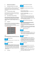
.1.2 ■ Unpacking PV modules the photovoltaic generator. Only for PV modules packed in vertical position High DC voltages, even when the photovoltaic generator is disconnected, if the generator is earthed. Severe or fatal injuries from electric shock! • Using an underlay, incline the pallet (e.g. with a beam, height approx. 10 cm for 5° inclination), so that the opening on the front of the box is elevated. The modules then lean back in the box which makes it easier to remove them.
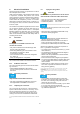
Mechanical Installation 5.4.1 5.1 Mounting orientation for PV modules NWEIS Leave a minimum clearance when mounting PV modules. This prevents mechanical tension due to thermal expansion. For roof top installations, install the PV modules on fire resistant roofs only. Please note that additional fire proofing might be required, depending on local building / fire codes. 5.1.
6.2 Electrical installation All relevant electrical values are specified on the backside nameplate of the module. Under normal conditions, a photovoltaic module is likely to experience conditions that produce more current and/or voltage than reported at standard test conditions. Accordingly, the values of Isc and Voc marked on the module should be multiplied by a factor of 1.
If you earth the PV module frame, the only task of this earth is the potential equalisation between the PV module frame and the supporting structure. 6.5 PV modules of the same type can be connected in parallel. The PV modules in this series are fundamentally designed for series connection. • Only use PV modules of the same type and output for parallel connection. Take measures for overcurrent protection (e.g. line fuses) if necessary.
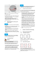
7.2 Clamp mounting for PV modules 7.2.1 Arranging the clamps ■ Permissible arrangement Fig. 5 Permissible clamp arrangement for framed modules a: b: c: d: Symmetrical clamping on the long sides Asymetrical clamping on the long sides Symentrical clamping on the short sides Asymetrical clamping on the short sides ■ Impermissible alignment Fig. 8 Definition of clamp length and depth for framed PV modules a: Clamp length, b: Clamp depth.
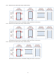
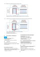
1100 Pa 1100 Pa (Ca. 110kg/m2, 110kg/m2) 7.6.1.1 Maximum load: 1100Pa (wind/ snow), 1100Pa (suction) Fig. 9a Mounting drawings for load level 1100Pa/1100Pa All dimensions are shown in mm. Permissible clamping area shown as red crosses. (Ca. 160kg/m2, 110kg/m2) 1600 Pa 1100 Pa 7.6.1.2 Maximum load: 1600Pa (wind/ snow), 1100Pa (suction) 100 100 Fig. 9b Mounting drawings for load level 1600Pa/1100Pa All dimensions are shown in mm. Permissible clamping area shown as red crosses. 1600 Pa 1600 Pa (Ca.
(Ca. 240kg/m2, 240kg/m2) Pressure 2400 Pa Suction 2400 Pa 7.6.1.4 Maximum load: 2400Pa (wind/ snow), 2400Pa (suction) Fig. 9d Mounting drawings for load level 2400Pa/2400Pa All dimensions are shown in mm. Permissible clamping area shown as red crosses. 7.6.2 Tested snow load (The modules have passed the test of 5400Pa in accordance with IEC61215) Fig. 9e Mounting drawings for tested snow load of 5400Pa All dimensions are shown in mm.
• Measure the insulation resistance RIS (7, 8) • Evaluate the annual power output and compare the data with earlier readings; • Create and archive a review report. • Check, repair or replace components, if required. cleaning agents. HINWEIS Dirt- or water-repellent coatings subsequently applied to the modules can negatively affect the efficiency of the PV modules and therefore the power output of the whole photovoltaic system. We therefore advise against the use of these agents. Refer to Ch. 8.
It is recommended to contract a specialised company to clean your photovoltaic generator properly without treading on the modules, if frequent cleaning is necessary. 8.5 Repairs 8.5.1 PV Modules For repairing PV modules, only use contract technicians who have been authorised by SHARP to avoid loss of warranty. A defective PV module can cause loss of output, as well as consequential damage. If a PV module needs repairing, first get in touch with SHARP.