Introduction MODEL XR-1X XR-1S Setup OPERATION MANUAL Quick Start MULTIMEDIA PROJECTOR Connections Basic Operation Useful Features (The picture shown above is of the XR-1S.
IMPORTANT For your assistance in reporting the loss or theft of your Projector, please record the Model and Serial Number located on the bottom of the projector and retain this information. Before recycling the packaging, please be sure that you have checked the contents of the carton thoroughly against the list of “Supplied accessories” on page 11. Model No.: Serial No.: SPECIAL NOTE FOR USERS IN THE U.K.
The supplied CD-ROM contains operation instructions in English, German, French, Swedish, Spanish, Italian, Dutch, Portuguese, Chinese (Traditional Chinese and Simplified Chinese) and Korean. Carefully read through the operation instructions before operating the projector. Die mitgelieferte CD-ROM enthält Bedienungsanleitungen in Englisch, Deutsch, Französisch, Schwedisch, Spanisch, Italienisch, Niederländisch, Portugiesisch, Chinesisch (Traditionelles Chinesisch und einfaches Chinesisch) und Koreanisch.
Introduction Introduction Before using the projector, please read this operation manual carefully. ENGLISH There are two important reasons for prompt warranty registration of your new SHARP Projector, using the REGISTRATION CARD packed with the projector. 1. WARRANTY This is to assure that you immediately receive the full benefit of the parts, service and labor warranty applicable to your purchase. 2.
The enclosed computer cable must be used with the device. The cable is provided to ensure that the device complies with FCC Class A verification. U.S.A. ONLY WARNING: This is a Class A product. In a domestic environment this product may cause radio interference in which case the user may be required to take adequate measures. WARNING: The cooling fan in this projector continues to run for about 90 seconds after the projector enters standby mode.
Introduction How to Read this Operation Manual ■ The specifications of the XR-1X are slightly different from those of the XR-1S, however, you can connect and operate both models in the same manner. This operation manual uses the XR-1S for the purpose of explanation. • In this operation manual, the illustration and the screen display are simplified for explanation, and may differ slightly from actual display. Using the Menu Screen The menu can be operated to achieve two functions, adjustment and setting.
Contents Preparing Introduction Setup How to Read this Operation Manual .... 3 Contents ............................................... 4 IMPORTANT SAFEGUARDS ............... 6 How to Access the PDF Operation Manuals ............................................ 10 Accessories ........................................ 11 Part Names and Functions ................. 12 Setting up the Projector ...................... 18 Inserting the Lithium Battery ................ 14 Usable Range ...........................
Introduction Reference Appendix Maintenance ....................................... 52 Maintenance Indicators ...................... 53 Regarding the Lamp ........................... 55 Lamp ..................................................... 55 Caution Concerning the Lamp ............ 55 Replacing the Lamp ............................. 55 Removing and Installing the Lamp Unit .................................... 56 Resetting the Lamp Timer .................... 57 Connecting Pin Assignments ............
IMPORTANT SAFEGUARDS CAUTION: Please read all of these instructions before you operate this product and save these instructions for later use. Electrical energy can perform many useful functions. This product has been engineered and manufactured to assure your personal safety. BUT IMPROPER USE CAN RESULT IN POTENTIAL ELECTRICAL SHOCK OR FIRE HAZARDS. In order not to defeat the safeguards incorporated in this product, observe the following basic rules for its installation, use and servicing. 1.
Do not overload wall outlets, extension cords, or integral convenience receptacles as this can result in a risk of fire or electric shock. 16. Object and Liquid Entry Never push objects of any kind into this product through openings as they may touch dangerous voltage points or short-out parts that could result in a fire or electric shock. Never spill liquid of any kind on the product. 17.
Be sure to read the following safeguards when setting up your projector. Caution concerning the lamp unit ■ Potential hazard of glass particles if lamp ruptures. In case of lamp rupture, contact your nearest Sharp Authorized Projector Dealer or Service Center for a replacement. See “Replacing the Lamp” on page 55. ■ When placing the projector in a high position, be sure to secure it carefully to avoid personal injury caused by the projector falling down.
■ When transporting the projector, be sure not to subject it to hard impact and/or vibration, as this can result in damage. Take extra care with the lens. Before moving the projector, be sure to unplug the power cord from the wall outlet, and disconnect any other cables connected to it. ■ Do not carry the projector by holding the lens. ■ When transporting the projector, be sure to place the projector in the supplied soft case. (See page 11.
How to Access the PDF Operation Manuals PDF operation manuals in several languages are included in the CD-ROM, so that you can work with the projector, even if you do not have this manual. To utilize these manuals, you need to install Adobe Reader on your computer (Windows or Macintosh). Please download Adobe Reader from the Internet (http://www.adobe.com). Accessing the PDF Manuals For Windows: 1 Insert the CD-ROM in the CD-ROM drive. 2 Double click the “My Computer” icon.
Introduction Accessories Supplied accessories Lithium battery (CR2025) UBATL0011TAZZ Remote control RRMCGA256WJSA Soft case GCASNA011WJZZ Cable tieK2 UBNDTA015WJZZ RGB/USB cable (6' (1.8 m)) QCNWGA047WJPZ • For the RGB/USB cable • For the power cord • Projector manual CD-ROM UDSKAA045WJN1 • Operation manual (this manual) Power cord* (1) (2) For U.S., Canada, etc. (6' (1.8 m)) QACCDA029WJPZ For Europe, except U.K. (6' (1.8 m)) QACCVA006WJPZ (3) (4) For U.K.
Part Names and Functions Numbers in Z refer to the main pages in this operation manual where the topic is explained. Projector Top View Lamp indicator 54 ON/STANDBY button For turning the power on and putting the projector into standby mode. 26 54 ENTER button For setting items selected or adjusted on the menu. Adjustment buttons (W/Y/V/X) For selecting menu items. 36 27 Setup Guide indicators 54 Temperature warning indicator Volume buttons (V/X) For adjusting the speaker sound level.
Side View Terminals Refer to “INPUT Terminals and Connectable Main Equipment” on page 21. INPUT 1 terminal 23 Terminal for computer RGB and component signals. USB terminal Terminal connecting with the USB terminal on the computer for using the supplied remote control as the computer mouse. AC socket Connect the supplied Power cord. 33 24 INPUT 2 terminal Terminal for connecting video equipment with an S-video terminal. 25 INPUT 3 terminal Terminal for connecting video equipment.
Part Names and Functions (Continued) Numbers in Z refer to the main pages in this operation manual where the topic is explained. ON/STANDBY button For turning the power on and putting the projector into standby mode. 26 INPUT 1, 2, and 3 buttons For switching to the respective input modes. 29 AUTO SYNC button For automatically adjusting images when connected to a computer. 32 RESIZE button For switching the screen size (NORMAL, BORDER, etc.). 30 PICTURE MODE buttons For switching the picture mode.
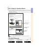
Front view 30° The remote control can be used to control the projector within the ranges shown in the illustration. Note • The signal from the remote control can be reflected off a screen for easy operation. However, the effective distance of the signal may differ depending on the screen material. When using the remote control • Be sure not to drop, expose to moisture or high temperature. • The remote control may malfunction under a fluorescent lamp.
Quick Start This section shows the basic operation (projector connecting with the computer). For details, see the page described below for each step. Setup and Projection In this section, connection of the projector and the computer is explained using one example. 5 INPUT button 4 ENTER button 3 6 4 3 6 ON/STANDBY button HEIGHT ADJUST button 4 Zoom knob 4 Focus ring ON/STANDBY button 5 INPUT 1 button 4 ENTER button 1. Place the projector facing a wall or a screen _P. 18 2.
4. Adjust the projected image with the Setup Guide 1 After the projector turns on, the Setup 3 Angle (See page 28.) Guide appears. (When “Setup Guide” is set to “On”. n page 45) • Adjust the projector angle using the HEIGHT ADJUST button. Quick Start HEIGHT ADJUST button 4 Zoom (See page 28.) • Refer to the Setup Guide screen to adjust the focus, angle and zoom. • Press TENTER to finish the Setup Guide. 2 Focus (See page 27.) • Bring the projected image into focus using the focus ring.
Setting up the Projector Setting up the Projector Position the projector perpendicular to the screen with the projector’s feet flat and level to achieve an optimal image. Note • For an optimal image, position the screen so that it is not in direct sunlight or room light. Light falling directly on the screen washes out the colors, making viewing difficult. Close the curtains and dim the lights when setting up the screen in a sunny or bright room.
Screen Size and Projection Distance (XR-1X) NORMAL Mode (4:3) Picture (Screen) size Diag. [χ ] Width Height Projection distance [L] Minimum [L1] Maximum [L2] Distance from the bottom of the image to the lens center [H] ⳮ50.9 cm (ⳮ20 3/64⬙) 270⬙ (686 cm) 549 cm (216⬙) 411 cm (162⬙) 9.9 m (32⬘ 5⬙) 250⬙ (635 cm) 508 cm (200⬙) 381 cm (150⬙) 9.1 m (30⬘ 0⬙) 200⬙ (508 cm) 406 cm (160⬙) 305 cm (120⬙) 7.3 m (24⬘ 0⬙) 8.5 m (28⬘ 0⬙) ⳮ37.7 cm (ⳮ14 150⬙ (381 cm) 305 cm (120⬙) 229 cm (90⬙) 5.5 m (18⬘ 0⬙) 6.
Setting up the Projector (Continued) Screen Size and Projection Distance (XR-1S) NORMAL Mode (4:3) Picture (Screen) size Diag. [χ ] Width Height Projection distance [L] Minimum [L1] Maximum [L2] Distance from the bottom of the image to the lens center [H] ⳮ61.5 cm (ⳮ24 7/32⬙) 280⬙ (711 cm) 569 cm (224⬙) 427 cm (168⬙) 9.8 m (32⬘ 2⬙) 250⬙ (635 cm) 508 cm (200⬙) 381 cm (150⬙) 8.8 m (28⬘ 9⬙) 200⬙ (508 cm) 406 cm (160⬙) 305 cm (120⬙) 7.0 m (23⬘ 0⬙) 8.1 m (26⬘ 8⬙) ⳮ43.
Connections INPUT Terminals and Connectable Main Equipment INPUT 1 terminal ■ Connecting the computer. (See page 23.) ■ Connecting video equipment with component output terminal (DVD player, DTV decoder, DVD recorder with hard disc, etc.). (See page 24.) INPUT 2 terminal Connecting video equipment with S-video output terminal (VCR, DVD player, etc.). (See page 24.) INPUT 3 terminal Connecting video equipment without S-video output terminal. (See page 25.
Samples of Cables for Connection • For more details of connection and cables, refer to the opeation manual of the connecting equipment. • You may need other cables or connectors not listed above. Equipment Computer Input Signal RGB/USB cable (supplied) Terminal on the projector INPUT1 ø3.5 mm stereo audio cable AUDIO INPUT 3 RCA (Component) to 15-pin D-sub cable (optional, AN-C3CP) INPUT1 S-video cable (commercially available) INPUT2 Video cable (commercially available) INPUT3 ø3.
Connecting to a Computer Before connecting, be sure to unplug the power cord of the projector from the AC outlet and turn off the devices to be connected. After making all connections, turn on the projector and then the other devices. When connecting a computer, be sure that it is the last device to be turned on after all the connections are made. Be sure to read the operation manuals of the devices to be connected before making connections.
Connecting to Video Equipment The projector has a COMPUTER/COMPONENT terminal, an S-VIDEO terminal and a VIDEO terminal for video input. See the illustration below to connect with the audio-visual equipment. The image quality is highest in order of the component signal, the S-video signal and the video signal. If your audio-visual equipment has a component output terminal, use the COMPUTER/ COMPONENT terminal (INPUT1) on the projector for video connection.
When using a composite video cable To audio output terminal To video output terminal To INPUT3 To AUDIO terminal INPUT terminal ø3.5 mm minijack to RCA audio cable (commercially available) Composite video cable (commercially available) Connections Note • ø3.5 mm minijack to RCA audio cable (commercially available) is required for audio input. Connecting the Power Cord Plug the supplied power cord into the AC socket on the side of the projector.
Turning the Projector On/Off Info Turning the Projector on Before performing the steps in this section, connect any equipment that you use with the projector. (See pages 23, 24 and 25.) Also connect the power cord to the projector. (See page 25.) Press SON/STANDBY on the projector or AON/STANDBY on the remote control. • English is the factory default language. If you want to change the on-screen display to another language, change the language according to the procedure on page 46.
Image Projection About the Setup Guide Setup Guide screen After turning on the projector, the Setup Guide screen appears to assist you with projector setup. Guidance items 1 FOCUS 2 HEIGHT ADJUST 3 ZOOM Adjust the projector by following the illuminated buttons or Setup Guide indicators. Press TENTER to turn off the Setup Guide screen. Note • The Setup Guide screen automatically highlights the items in order of 1 FOCUS 2 HEIGHT ADJUST 3 ZOOM 4 ENTER .
Image Projection (Continued) 2 Adjusting the Height HEIGHT ADJUST button The height of the projector can be adjusted using the adjustment feet at the front and rear of the projector. When the screen is in a higher position than the projector, the projection image can be made higher by adjusting the projector. 1 Lift the projector to adjust its height while pressing the HEIGHT ADJUST button. 2 Remove your hands from the HEIGHT ADJUST button of the projector after its height has been finely adjusted.
Switching the Input Mode INPUT buttons Select the appropriate input mode for the connected equipment. AV MUTE button PressC INPUT 1, D INPUT 2 or EINPUT 3 on the remote control to select the input mode. Volume buttons • When pressing INPUT (W/Y) on the projector, input mode switches in order of INPUT1 INPUT2 INPUT3 . • When “Auto Search” is set to “On”, INPUT (W/ Y) on the projector functions as the Auto Search buttons. (See page 47.
Image Projection (Continued) Resize Mode This function allows you to modify or customize the resize mode to enhance the input image. Depending on the input signal, you can choose “NORMAL”, “BORDER” or “STRETCH” image. Press HRESIZE. • See page 43 for setting on menu screen.
VIDEO • “STRETCH” is fixed when 540P, 720P or 1080I signals are entered. Input Signal DVD / Video Output screen image Image type NORMAL BORDER STRETCH 4:3 aspect ratio 480I, 480P, NTSC, PAL, SECAM Letter box Squeezed 16:9 image Squeezed 4:3 image 16:9 aspect ratio 16:9 aspect ratio (4:3 aspect ratio in 16:9 screen) Basic Operation 540P, 720P, 1080I (16:9) * Mode for projecting an image with the original aspect ratio without cutting any portions.
Adjusting/Operating with the Remote Control Auto Sync (Auto Sync Adjustment) Auto Sync function works when detecting input signal after the projector turns on. Press FAUTO SYNC to manually adjust with Auto Sync function. Note • When the optimum image cannot be achieved with Auto Sync adjustment, use the help menu for manual adjustments. (See page 51.) Freezing a Moving Image 1 2 Press NFREEZE. • The projected image is frozen.
Using Mouse Function When connecting the projector and computer with the USB terminals, you can use the remote control as the computer mouse. Supplied accessory To RGB output terminal RGB/USB Cable To USB terminal To USB terminal To INPUT1 terminal RGB/USB Cable 1 Connect the projector and the computer with the supplied RGB/ USB cable. 2 Use the mouse functions. Note • you can not use this function when displaying the menu screen.
Menu Items The following shows the items that can be set in the projector.
Main menu “PRJ - ADJ” menu PRJ - ADJ Page 47 Picture SCR - ADJ PRJ - ADJ Eco/Quiet Mode Auto Search Auto Power Off Guide LEDs System Sound System Lock Help Sub menu Eco/Quiet Mode [On/Off] Page 47 Auto Search [On/Off] Page 47 On On On On On Auto Power Off [On/Off] Page 48 Guide LEDs [On/Off] Page 48 System Sound [On/Off] Page 50 System Lock Lamp Timer(Life) SEL./ADJ.
Using the Menu Screen The menu can be operated to achieve two functions, adjustment and setting. (For setting the menu items, see pages 38 and 39.) Operating with the projector When “PRJ - ADJ” - “Guide LEDs” is set to “On”, the buttons used for menu adjustment on the projector light up. Example: When W, Y and the MENU/HELP button light up on the projector, you can use those buttons for operation.
3 Press P or R to select the item you want to adjust. • The selected item is highlighted. Picture SCR - ADJ Picture Mode Contrast Bright Red Blue CLR Temp Bright Boost sRGB Reset PRJ - ADJ Help Standard 0 0 0 0 7500K Off Off SEL./ADJ. Single ADJ END Single adjustment items Picture SCR - ADJ Resize Image Shift Keystone Auto Keystone PRJ - ADJ Help Normal 0 0 Off To adjust the projected image while watching it Press IENTER. • The selected single adjustment item (e.g.
Using the Menu Screen (Continued) The menu can be operated to achieve two functions, adjustment and setting. (For adjusting the menu items, see pages 36 and 37.) MENU/HELP button MOUSE Adjustment button (P/R/O/Q) ENTER button RETURN button Menu Selections (Settings) Example: Setting “Background”. •This operation can also be performed by using the buttons on the projector. 1 Press BMENU. 2 Press O or Q to display the other menu screen.
3 Press P or R to select the item you want to set, and then press IENTER or Q to display the sub menu. •The selected item is highlighted. Note • Press JRETURN or O to return to the previous screen. 4 Press P or R select the setting of the item displayed in the sub menu. Picture Picture SEL./ADJ. Press IENTER. 6 Press BMENU. PRJ - ADJ Help Normal 0 0 Off On Logo Blue None On Front English SEL./ADJ.
Picture Adjustment (“Picture” menu) You can adjust the projector’s picture to your preferences using the “Picture” menu. Selecting the Picture mode Adjusting the Image Menu operation n Page 38 Menu operation n Page 36 Q Example: “Picture” screen menu for INPUT 1 (RGB) mode Q Example: “Picture” screen menu for INPUT 1 (RGB) mode Picture SCR - ADJ Picture Mode Contrast Bright Red Blue CLR Temp Bright Boost sRGB Reset PRJ - ADJ Help 0 0 0 0 7500K Off Off SEL./ADJ.
Adjusting the Color Temperature Emphasizing the Contrast This function emphasizes the bright portions of images to obtain a higher contrast image. Menu operation n Page 36 Menu operation n Page 38 Q Example: “Picture” screen menu for INPUT 1 (RGB) mode Q Example: “Picture” screen menu for INPUT 1 (RGB) mode Picture SCR - ADJ Picture Mode Contrast Bright Red Blue CLR Temp Bright Boost sRGB Reset SEL./ADJ.
Picture Adjustment (“Picture” menu) (Continued) Progressive sRGB Setting Menu operation n Page 38 Menu operation n Page 38 Q Example: “Picture” screen menu for INPUT 2 mode Q Example: “Picture” screen menu for INPUT 1 (RGB) mode Picture SCR - ADJ Picture Mode Contrast Bright Color Tint Sharp CLR Temp Bright Boost Progressive Reset SEL./ADJ. PRJ - ADJ Help Standard 0 0 0 0 0 7500K Off 3D Progressive ENTER END Picture Picture Mode Contrast Bright Red Blue CLR Temp Bright Boost sRGB Reset SEL.
Adjusting the Projected Image (“SCR - ADJ” menu) You can adjust the projected image and on-screen display to your preferences using the “SCR ADJ” menu. Setting the Resize Mode Adjusting the Image Position You can move the projected image vertically. Menu operation n Page 38 Picture Resize Image Shift Keystone Auto Keystone OSD Display Background Setup Guide PRJ Mode Language SEL./ADJ.
Adjusting the Projected Image (“SCR - ADJ” menu) (Continued) Keystone Correction Setting On-screen Display When the image is projected either from the top or from the bottom towards the screen at an angle, the image becomes distorted trapezoidally. The function for correcting trapezoidal distortion is called Keystone Correction. This function allows you to turn the on-screen messages on or off.
Selecting the Background Image Setting the Setup Guide You can set the Setup Guide screen during the projector startup. Menu operation n Page 38 Picture SCR - ADJ Resize Image Shift Keystone Auto Keystone OSD Display Background Setup Guide PRJ Mode Language Menu operation n Page 38 PRJ - ADJ Help Picture 0 0 Off On Logo On Front English SEL./ADJ.
Adjusting the Projected Image (“SCR - ADJ” menu) (Continued) Reversing/Inverting Projected Selecting the On-screen Display Images Language The projector can switch the on-screen display language among 11 languages. Menu operation n Page 38 Picture SCR - ADJ Resize Image Shift Keystone Auto Keystone OSD Display Background Setup Guide PRJ Mode Language Menu operation n Page 38 PRJ - ADJ Help 0 0 Off On Logo On Front English SEL./ADJ.
Setting the Projector Function (“PRJ - ADJ” menu) You can use the “PRJ - ADJ” menu to enhance the usage for the projector. Eco/Quiet Mode Auto Search Function Menu operation n Page 38 Picture SCR - ADJ PRJ - ADJ Eco/Quiet Mode Auto Search Auto Power Off Guide LEDs System Sound System Lock Help On On On On On Lamp Timer(Life) SEL./ADJ.
Setting the Projector Function (“PRJ - ADJ” menu) (Continued) Auto Power Off Function Setting the Guide LEDs Menu operation n Page 38 Picture SCR - ADJ Menu operation n Page 38 PRJ - ADJ Eco/Quiet Mode Auto Search Auto Power Off Guide LEDs System Sound System Lock Lamp Timer(Life) SEL./ADJ. Help 0 h ENTER 100% PRJ - ADJ SEL./ADJ.
System Lock Function This function prevents unauthorized use of the projector. Once this function is activated, users must enter the correct keycode each time the projector is turned on. We suggest you record the keycode in a safe place where only authorized users have access.
Setting the Projector Function (“PRJ - ADJ” menu) (Continued) Setting the Confirmation Sound Checking the Lamp Life Status You can confirm the cumulative lamp usage time and the remaining lamp life (percentage). Menu operation n Page 38 Picture SCR - ADJ Menu operation n Page 36 PRJ - ADJ Eco/Quiet Mode Auto Search Auto Power Off Guide LEDs System Sound System Lock Lamp Timer(Life) SEL./ADJ.
Troubleshooting with “Help” menu This function advises you to solve the problems during usage. MENU/HELP button Displaying “Help” menu screen Adjuatment button (P/R/O/Q) ENTER button Example: When image flickering appears Operation to solve image flickering when projecting the computer RGB signal. 1 Press BMENU/HELP. 4 Select “Initiate “Auto Sync” Adjustments”, then press IENTER. 2 Press O or Q to select “Help”, then press IENTER. 5 If the image is not improved, select “Adjust horizontal noise.
Maintenance Cleaning the projector ■ Be sure to unplug the power cord before cleaning the projector. ■ The cabinet as well as the operation panel is made of plastic. Avoid using benzene or thinner, as these can damage the finish on the cabinet. ■ Do not use volatile agents such as insecticides on the projector. Do not attach rubber or plastic items to the projector for long periods. The effects of some of the agents in the plastic may cause damage to the quality or finish of the projector.
Maintenance Indicators ■ The warning lights (ON/STANDBY button, lamp indicator and temperature warning indicator) on the projector indicate problems inside the projector. ■ If a problem occurs, either the temperature warning indicator or the lamp indicator will illuminate red, and the projector will enter standby mode. After the projector has entered standby mode, follow the procedures given below.
Maintenance Indicators (Continued) Maintenance indicator Temperature warning indicator Lamp indicator Power button Normal Abnormal Off Red on (Standby) Green on (Green blinks when the lamp is warming up.) Green on/ Red on Problem The internal temperature is abnormally high. Cause Possible Solution • Blocked air intake • Relocate the projector to an area with proper ventilation.
Regarding the Lamp Lamp ■ It is recommended that the lamp (sold separately) be replaced when the remaining lamp life becomes 5% or less, or when you notice a significant deterioration in the picture and color quality. The lamp life (percentage) can be checked with the on-screen display. (see page 50) ■ Purchase a replacement lamp of type AN-XR1LP from your place of purchase, nearest Sharp Projector Dealer or Service Center. IMPORTANT NOTE TO U.S.
Regarding the Lamp (Continued) Removing and Installing the Lamp Unit Info • Be sure to remove the lamp unit using the handle. Be sure not to touch the glass surface of the lamp unit or the inside of the projector. • To avoid injury to yourself and damage to the lamp, be sure to carefully follow the steps below. • Do not loosen other screws except for the lamp unit cover and lamp unit.
4 Remove the lamp unit. 5 Insert the new lamp unit. 6 Handle • Loosen the securing screws from the lamp unit. Hold the lamp unit by the handle and pull it in the direction of the arrow. At this time, keep the lamp unithorizontal and do not tilt it. • Press the lamp unit firmly into the lamp unit compartment. Fasten the securing screws. Securing screws Replace the lamp unit cover. • Align the tab on the lamp unit cover (1)and place it while pressing the tab (2) to close it.
Connecting Pin Assignments INPUT 1 RGB Signal Terminal: 15-pin Mini D-sub female connector 11 15 1 6 5 10 RGB Input Component Input 1. 2. 3. 4. 5. 6. 7. 8. 9. 10. 11. 12. 13. 14. 15. 1. 2. 3. 4. 5. 6. 7. 8. 9. 10. 11. 12. 13. 14. 15.
Computer Compatibility Chart Computer • Multiple signal support • Compatible with the signals below in Horizontal Frequency: 15-70 kHz, intelligent compression Vertical Frequency: 45-85 Hz, XR-1X: SXGA, SXGA+ Pixel Clock: 12-108 MHz XR-1S: XGA, SXGA, SXGA+ Sync signal:Compatible with TTL level • Intelligent Compression and Expansion • Compatible with sync on green signal System resizing technology The following is a list of modes that conform to VESA.
Troubleshooting Problem Check Page • Projector power cord is not plugged into the wall outlet. 25 • Power to the external connected devices is off. – • The selected input mode is wrong. 29 • Cables incorrectly connected to the projector. 23, 24, 25 • Remote control battery has run out. 14, 15 No picture and no sound • External output has not been set when connecting notebook computer. or projector does not start. • The lamp unit cover is not installed correctly.
Problem Picture is green on INPUT 1 COMPONENT. Check • Change the input signal type setting. 51 Picture is pink (no green) on INPUT 1 RGB. Picture is too bright and whitish. • Image adjustments are incorrectly set. The cooling fan becomes • When temperature inside the projector increases, the cooling fan runs faster. noisy. The lamp does not light up even after the projector turns on. Page 40 – • The lamp indicator is illuminating in red. Replace the lamp.
For SHARP Assistance If you encounter any problems during setup or operation of this projector, first refer to the “Troubleshooting” section on pages 60 and 61. If this operation manual does not answer your question, please contact the SHARP Service departments listed below. U.S.A. Sharp Electronics Corporation 1-888-GO-SHARP (1-888-467-4277) Benelux SHARP Electronics Benelux BV 0900-SHARPCE (0900-7427723) Nederland 9900-0159 Belgium http://www.sharp.nl http://www.sharp.be http://www.sharp.
Specifications As a part of policy of continuous improvement, SHARP reserves the right to make design and specification changes for product improvement without prior notice. The performance specification figures indicated are nominal values of production units. There may be some deviations from these values in individual units. 63 Appendix Product type Projector Model XR-1X / XR-1S Video system NTSC3.58/NTSC4.
Dimensions Units: inches (mm) 4 13/16 (122) 9 47/64 (247) 2 17/32 (64) 1 19/32 (40.3) 1 9/64 (28.7) XR-1X 2 7/32 (56) 6 11/32 (161) 1 15/16 (49) 7 5/64 (179.5) 2 43/64 (67.5) 2 17/32 (64) 1 27/64 (36) 1 5/16 (33) XR-1S 2 7/32 (56) 6 11/32 (161) 7 5/64 (179.5) 1 15/16 (49) 2 43/64 (67.5) 3 59/64 (99.3) 4 1/2 (114.3) 19 /32 (15) 4 47/64 (120) 8 9/32 (210) 64 / (18.
Index AC socket .................................................. 25 Accessories .............................................. 11 Adjustment buttons ................................... 36 Adjust vertical noise ........................... 35, 51 Aspect ratio ............................................... 30 AUDIO INPUT terminal ................. 23, 24, 25 Auto Keystone Correction ........................ 44 Auto Power Off ......................................... 48 Auto Search ..........................
SHARP CORPORATION