
Specifications


the higher frequencies received, while
maintaining lower gain settings for the lower
frequencies. This is important for proper
alignment and triggering with changing data
edges so as to ensure consistent video
recovery.
Looking back at our earlier example we
used for calculating maximum cable length,
our cable run was 300 feet for a 10dB loss
cable at 135 MHz at 100 feet. Now, if we
have a less sensitive receiver, say the 20dB
type, our drive distance will decrease to 20dB
divided by 10dB times 100 feet, or, only 200
feet. You can see there is a ratio of 2/3 here.
This nominal 10dB performance spread in
receivers severely limits SDI cable run lengths.
Remember, all things being equal, pay
careful attention to receiver sensitivity and
cable attenuation specs for realizing the
most from SDI signal distribution. While
good routers utilize re-clocking, the need for
this feature primarily depends on the size
and complexity of your system design. Be
aware that good signal sources, routers, and
proper cable routing techniques help reduce
the invasion of signal jitter.
Footnotes:
1.
Measuring Wander in Video
Distribution Systems,
by Tom Tucker,
Tektronix (http://www.Tektronix.com/
Measurement/App_Notes/Published_
Articles/measwander/index.html)
2.
Monitoring in the Digital Environment,
by Ted Gary, Broadcast Engineering,
November 1999 (http://www.broadcastengin
eering.com/archives/1199/199911be40.html)
March/April 2001 ExtroNews 12.2 9
TECHNICALLY SPEAKING...
millivolts peak-to-peak, it is not much
different in level than standard video signals.
SDI is uni-directional and has a good signal-
to-noise recovery budget. So, with care,
smaller, local routing systems can work on a
budget without re-clocking.
Got The Jitters?
Signal jitter is another culprit in SDI
systems. Maintenance of the timing
relationship to a common timing reference
provides auto-phasing recovery circuits in
the receiver the ability to lock onto and
decode the clock and video data. When an
external factor, such as random noise,
affects the absolute bit timing, the receiver
encounters difficulty recovering clock and
data. Cable loss affects the amplitude of the
SDI signal while jitter affects the zero
crossing point of the data edges. The data
edges appear to dance back and forth with
random uncertainty. There is a jitter budget
allowance, but since noise and jitter effects
can become generally random, bit error rate
can creep up periodically and cause lost
data. If the jitter budget is exceeded, data
cannot be recovered at all.
As with analog signals, once you have
noise in the signal, it is extremely difficult
and costly to remove. Jitter caused by
induced noise effects, unstable signal
sources, or poor re-clocking systems is the
demise of digital signals. Sometimes, basic
signal attenuation effects are mistaken as
signal jitter. SDI signals contain a range of
low to high frequencies like analog signals.
Cable attenuation still affects the high
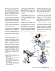
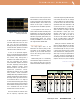
frequencies most. When looking at an eye
pattern, the data zero crossing point
(risetime/falltime area) appears wider than
normal. The eye pattern is typically used to
evaluate signal quality including jitter. This
appears to smear the data edges and look as
though large amounts of jitter are present,
when, in fact, measurement with SDI
measurement equipment may show the
signal well within jitter specifications. Jitter
measurements should be made with
instrumentation capable of proper
measurement. SMPTE Engineering
Guideline, EG-33-1998, Jitter Characteristics
and Measurements provides in-depth help
for this task (www.smpte.org). See
Figure 3.
Born To Wander
With the deployment of more digital video
networks, the monitoring of video sync
timing is more critical than before. In some
applications, where time-base correctors or
frame synchronizers are not used, problems
with image shifts and hue errors may occur
because of network induced wander of sync
and color burst timing. This condition creates
“video wander,” which is defined as sync
signal phase variations below 10 Hertz.
When the video signal is converted to
composite, this effect is not easy to remove.
1
Specialized television test equipment, such as
the Tektronix VM700T, can easily measure
horizontal sync timing jitter and wander for
serial digital systems.
Digital Safety Net
All of the aforementioned situations in
addition to poor connections and improper
terminations can cause data bit errors to
occur. A bit error is defined as a change in
one or more data values occurring between
the source and destination. SDI includes an
error detection and handling (EDH) system
that can monitor data quality and provide
some visibility of errors as well as location.
Some bit errors may not affect picture quality
directly but may signal impending failure.
Groupings of bit errors may affect picture
quality, sound, or both. SDI equipment will
typically incorporate some level of EDH
reporting or troubleshooting capability.
2
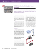
Receivers – Some Are So Insensitive To
Your Needs
SMPTE 259M mentions a typical range of
expected SDI receiver sensitivity between
20dB and 30dB at one-half the data clock
frequency. Further, proper cable equalization
should be employed. What is cable
equalization? It is a feature of the receiver’s
front-end amplifier that adjusts its gain to
compensate for higher losses in the signal at
Figure 3. Eye pattern shows normal cable losses,
yet jitter is still well within specs.