
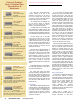
Specifications


March/April 2001 ExtroNews 12.2 7
of cables. Having all data bits organized as
one stream means there will be no issues
with clock and data synchronization.
Managing bit timing and cable equalization
is easier. Data skew problems encountered
with multi-conductor cables do not exist.
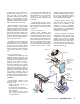
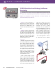
As seen in the operational diagram,
Figure 1, the SDI format utilizes a differential
signaling technique and NRZI (non-return to
zero inverted) coding. Although SDI is
transmitted as an unbalanced signal on 75-
ohm coax, transmission and reception
involves differential amplifiers that format
and detect, respectively, both data phases.
Utilizing differential reception creates
additional headroom and robustness in
signal-to-noise performance. Pseudo-
randomizing the data bits and use of NRZI
coding increases channel transmission
reliability. NRZI coding is desirable because its
operation is independent of signal polarity. In
this coding scheme, high and low levels do
not communicate data 1s or 0s. High and
low states are detected simply by the change
from one level to another. A zero means that
the transmission level stays the same, while a
one is transmitted each time the level
transitions from one level to the other.
SDI is more immune to extraneous noise
and low frequency components (hum)
because the receiver takes one phase of the
data transmission, inverts it, and then adds it
to the in-phase portion. Like a regular analog
differential amplifier, common mode noise
induced into the signal is cancelled out
during this inversion and addition operation.
So, what problems do exist? As in life, all
modes of travel have distinct advantages and
disadvantages. One must weigh the relative
difference. Key factors affecting SDI are cable
attenuation, signal jitter, signal wander, error
detection/handling (EDH), and receiver
sensitivity. See
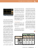
Table 1 for a list of the SDI
rates supported within SMPTE 259M.
Cable Quality is Job 1
The single largest effect on SDI
transmission rests with the quality of cable
used relative to the transmission distance
required. Any 75-ohm coaxial cable may be
used for SDI. The big question is always:
“How far can I go?”
SMPTE 259M guides us in determining
cable transmission length. It states that, for a
class A receiver (the best type to have), the
maximum transmission distance is given by a
TECHNICALLY SPEAKING...
continued on next page
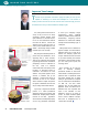
Figure 2. Standard reference level SDI signal
conforming to SMPTE 259M
Table 1. SMPTE 259M transmission rates and specifications
coaxial cable length having 30dB attenuation
at one-half the SDI clock rate. For example,
at the 270 Mbps rate for component NTSC,
one half the rate is 135 MHz. Many cable
specification tables show attenuation in dB
at 135 MHz since this is a popular rate.
Taking the attenuation value for a 100-foot
cable at 135 MHz and scaling it the 30dB
limit (attenuation is linear) gives us the
maximum cable length. If we have a
specified loss of 10dB at 135 MHz at
100 feet, then the maximum usable length
will be at 30dB divided by 10dB times
100 feet, which is 300 feet for that cable.
Utilizing the maximum calculated cable
length in a primary distribution run for SDI is
NOT a good idea. Suppose you have made
the maximum length run. Now, you connect
a 10-foot patch cable at the end to include
some other device and, suddenly, there is no
video image! You have just experienced the
“cliff effect.” When the loss parameters of
the SDI signal exceed the receiver’s ability to
recapture the data, the system completely