
Specifications

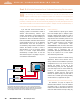


Correcting for delay skew can be done by
simply inserting additional cable in line with
one or more short pairs after the receiver has
output them on coax. See
Figure 3 (below).
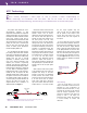
Return Loss Test
Return loss is a measurement of the
reflected signal back toward the transmitter.
This reflected energy is caused by variations of
impedance in the cable and connectors. See
Figure 4 (below). This would be the equivalent
of an electrical echo of the original signal. It is
like when your TV is switched to a weak station
and you see that the image is full of ghosts.
Near-End Crosstalk (NEXT)
The NEXT measurement is the amount of
signal that is induced into an adjacent twisted
pair at the transmission end by the
electromagnetic field created by the signal
being transmitted through an adjacent pair at
the same end. The untwisting of the cable
March/April 2001 ExtroNews 12.2 23
Wiremap Test
The Wiremap Test is used to identify
installation-wiring errors:
• Proper pin termination at each end
• Continuity to the remote end
• Shorts between any two or more
conductors
• Crossed pairs
• Split pairs
• Reversed pairs
• Any other mis-wiring.
Attenuation Test
The loss of signal strength (or voltage) in the
cable is called attenuation. The more
attenuation there is, the less signal there will
be present at the receiver. The attenuation is
measured in decibels (dB). Attenuation
increases with distance and frequency. For
every 6dB of loss, the original signal will be
half the original amplitude.
Length Test
Structured cable systems for the data world
have a length limit of 328 feet (100 meters)
total. (Note: this restriction does not directly
apply to the transmission of analog signals.)
The length test will provide us with the
physical length of each pair and the delay time
in nanoseconds.
The delay skew is the difference in time it
takes for a signal to travel down the shortest
pair to the time it takes to travel down the
longest pair. Lengths of wire pairs often vary
within the same UTP cable due to small
differences in twist tension and rates. The
delay skew is measured in nanoseconds (ns)
and feet.
Using Belden Media Twist cable for our
reference, each foot has a delay of 1.451 ns. If
there was a delay skew of five feet between a
pair of wires, the delay in nanoseconds would
be 7.255 (5 feet x 1.451 ns). This would be
very close to one pixel width off at the 1280 x
1024 rate and half a pixel width off at the
1024 x 768 rate. If this delay skew is not
compensated for, the image will appear to be
out of convergence because the red, green,
and blue signals will arrive at different times.
Delay skew is caused by differences in
length between one or more of the pairs.
TECH CORNER
CAT 5 T 15HD A
Transmitter
CAT 5 R BNC A
Receiver
C
A
T
5
T
1
5
H
D
A
H
-S
H
IFT
B
U
F
F
E
R
ED
C
O
M
P
U
T
E
R
IN
P
U
T
A
U
D
IO
ID PIN 4
ID PIN 11
L
O
C
A
L
M
O
N
IT
O
R
PC Computer
CAT 5 UTP Cable
Audio
LCD Projector
... THEN insert a three foot
extension cable to equalize
UTP skew for red video.
IF cable measurement
indicates that the pair
with wires
1 and 2
is
three feet shorter than
the other signals...
R
G
B
IN
P
U
T
R
G
B
O
U
T
P
U
T
R
G
B
H
/H
V
V
A
A
U
D
IO
L
B
SOG
C SYNC
P
O
W
E
R
1
5
V
.
5
A
D
C
L
R
that is required to make the termination
makes this the most vulnerable part of the
assembly process. Electromagnetic emissions
become greater with increases in the
frequency of the signal, and thus, crosstalk
increases with increases in frequency.
Equal Level Far-End Crosstalk (ELFEXT)
ELFEXT is a very important measurement
for our application. This is the crosstalk that
reaches the receiver and has automatically
had its results compensated for by variations
in cable length. A short run will have less
attenuation and therefore have a higher
Far-End Crosstalk (FEXT) reading than a
longer cable. The ELFEXT measurement
automatically adjusts the FEXT results for
the difference in cable lengths.
For the full UTP technology article,
please visit our web site at
http://www.extron.com/utptechnology.
Reflections (or Ghosts)
Main Signal Flow
SIGNAL
Figure 3.A length of coaxial cable is added to compensate for delay skew.
Figure 4. Reflected energy caused by impedance variations.