
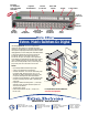
Specifications


22 ExtroNews 12.2 March/April 2001
the two inputs together. They will
cancel out and only the original signal
will be present at the output of the
receiver. This would still be true if the
common mode noise were negative at
both inputs.
If for any reason the wires in a twisted
pair were to become separated—like from a
sharp bend during installation—the noise
will strike the wires at slightly different
angles, causing the induced signals (noise)
to be slightly different in each wire. This
difference will not cancel out at the receiver
and, thus, will become part of the signal. At
the same time, this separation will form a
loop (See
Figure 2) and will act as a loop
antenna, picking up additional unwanted
noise/crosstalk.
Cable Testing
This is not a coax cable; it is not a “just
crimp on some BNC connectors and turn
everything on” type of application. As
people in the data world know, it is very
important that this cable run be tested to
meet the stringent requirements of the
Category 6 specification (the higher the
quality of cable is, the higher the
performance that results). The following
is a brief summary of common UTP
cable tests.
All induced common mode noise from
adjacent wire pairs, as well as from other
external sources such as motors,
transformers, and other external sources,
will cause the same noise signal to be
induced into both wires equally and of
the same polarity. This will cause
electrons to flow in the same direction
through both wires of the twisted pair,
and the noise will cancel at the receiver.
In balanced transmissions, the receiver is
operating in a differential mode. This
means it is looking for a difference
between the two input signals to form an
output signal. The receiver has a positive
and negative input, sometimes referred
to as the Tip and Ring inputs,
respectively. The differential receiver
performs a simple math function: it
inverts the sign (polarity) of the signal at
the negative input to a positive value and
adds the value of the two input signals
together.
When common mode noise is present
on the twisted pair, the noise is equal in
amplitude and always of the same
polarity on both wires. The differential
receiver processes this common mode
noise in the same way as it did the signal.
If we have +0.015 volts of common
mode noise at both inputs, change the
sign of the common mode noise at the
negative input to –0.015 volts, and add
One problem with twisted pair wire is
electromagnetic emissions at high
frequencies. These emissions can couple into
adjacent twisted pairs. The second issue is
the ability of the cable to eliminate common
mode noise. Common mode noise is
electrical interference induced into the cable
with equal amounts of energy, in the same
polarity, on both wires of a twisted pair.
This can come from sources like electric
motors, air chillers, power transformers,
fluorescent lighting ballasts, etc.
In a well-designed and balanced multi-
pair Category 5/5e/6 cable with consistent
twist ratios and matched pair lengths, the
electromagnetic interference (EMI) being
emitted from the pair is reduced
significantly. In addition, common mode
noise from external interference and
adjacent pair crosstalk is significantly
improved. To see how this is important, we
first must understand what happens when a
balanced signal is applied to a twisted pair
of wires. When a transmitter applies a
balanced analog audio or video signal to a
twisted pair wire, the signal is the same
amplitude (voltage level) on both wires, but
the signal on one of the wires is inverted to
the opposite polarity. When the signal on
one wire is going in a positive direction, the
signal on the other wire is going in a
negative direction. This is referred to as
differential mode. See
Figure 1.
UTP Technology
E
xtron recently developed a white paper on UTP to provide a better understanding of
UTP technology and installation and test issues. This can be found on our Web site at
http://www.extron.com/utptechnology. The following is a condensed version of the UTP white paper.
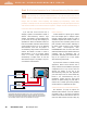
Voltage In Voltage Out
Positive Direction
Negative Direction
Common Mode
Noise
Figure 1. Common mode noise:The noise is at the same level traveling in the same
direction at the same time.The noise will cancel at the receiver.
TECH CORNER
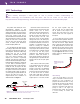
Figure 2.Twisted pair
showing damaged twist
pattern.