CD-C410H,CP-C410 SERVICE MANUAL No. S5728CDC410H/ CD-C410H CP-C410 CD-C410H and CP-C410 constitute CD-C410H. • In the interests of user-safety the set should be restored to its original condition and only parts identical to those specified be used. • Note for users in UK Recording and playback of any material may require consent which SHARP is unable to give.
CD-C410H,CP-C410 (Except for UK) SAFETY PRECAUTION FOR SERVICE MANUAL Precaution to be taken when replacing and servicing the Laser Pickup. The AEL (Accessible Emission Level) of Laser Power Output for this model is specified to be lower than Class I Requirements. However, the following precautions must be observed during servicing to protect your eyes against exposure to the laser beam.
CD-C410H,CP-C410 FOR A COMPLETE DESCRIPTION OF THE OPERATION OF THIS UNIT, PLEASE REFER TO THE OPERATION MANUAL. IMPORTANT SERVICE NOTES (FOR UK ONLY) WITHSTANDING VOLTAGE TESTER Before returning the unit to the customer after completion of a repair or adjustment it is necessary for the following withstand voltage test to be applied to ensure the unit is safe for the customer to use. Setting of Withstanding Voltage Tester and set.
CD-C410H,CP-C410 NAMES OF PARTS CD-C410H 1 Front Panel 1. Disc Tray 2. Disc Number Indicator 3. Timer Indicator 4. Record Indicator 5. Sleep Indicator 6. Extra Bass Indicator: X-BASS 7. Function/CD Track/CD Counter/Frequency/Preset Channel/Volume/Timer/Sleep Time Indicator 8. Memory Indicator 9. FM Stereo Mode Indicator: ST 10. FM Stereo Indicator: 11. CD Play Indicator: 12. CD Repeat Indicator: 13. CD Pause Indicator: 2 1 2 34 5 6 REC X-BASS 3 SLEEP 11 12 13 7 14. On/Stand-by Switch 15.
CD-C410H,CP-C410 CD-C410H Rear Panel 1. Video/Auxiliary (Audio Signal) Input Sockets 2. Speaker Terminals 3. AC Power Lead 4. FM 75 ohms Aerial Socket 5. AM Loop Aerial Input Socket 1 2 4 5 3 CP-C410 Speaker Section 6. Full Range Speaker 7. Bass Reflex Duct 8. Speaker Wire 6 7 8 1 Remote Control 1. Remote Control Transmitter LED CD Control section 2. Disc Number Select Buttons 3. Track Down/Review Button: 4. Track Up/Cue Button: 5. Disc Skip Button 6. Play/Repeat Button: 7. Stop Button: 8.
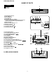
–6– 9 8 7 6 5 4 3 2 0:00 AM 0:00 TUNING/TIME ( ) MEMORY/ SET CLOCK ON/ STAND-BY AM 12:00 In this example, the clock is set for the 24-hour (0:00) system. SETTING THE CLOCK Press the ON/STAND-BY switch to enter the stand-by mode. or ) button to select the time Press the TUNING/TIME ( or ) button to adjust the minutes. Press the button for at least 0.5 seconds to change the time in 5 minute intervals. The hour setting will not advance even if minutes advance from "59" to "00".
CD-C410H,CP-C410 DISASSEMBLY Caution on Disassembly Follow the below-mentioned notes when disassembling the unit and reassembling it, to keep it safe and ensure excellent performance: 1. Take cassette tape and compact disc out of the unit. 2. Be sure to remove the power supply plug from the wall outlet before starting to disassemble the unit. 3. Take off nylon bands or wire holders where they need be removed when disassembling the unit.
CD-C410H,CP-C410 Display PWB ( K1 ) x4 ø3 x12mm Front Panel ( E1 ) x9 ø3 x10mm ( L1 ) x1 ø2.6 x10mm ( E1 ) x1 ø3 x10mm Shift Lever ( E2 ) x2 CD Changer Mechanism Tape Mechanism ( E1 ) x1 ø3 x8mm Main PWB ( E2 ) x1 CD Player Base CD Mechanism Care when installing the CD changer mechanism. Install the CD changer mechanism on the CD player base after the shift lever has been set in the highest position.
CD-C410H,CP-C410 REMOVING AND REINSTALLING THE MAIN PARTS CD MECHANISM SECTION Perform steps 1, 2, 3, 10 and 11 of the disassembly method to remove the CD mechanism. Loading Motor How to remove the loading motor (See Fig. 9-1) 1. Remove the screws (A1) x 2 pcs., to remove the loading motor. ( A1 ) x2 ø2 x5mm Figure 9-1 How to remove the pickup (See Fig. 9-2) 1. Remove the screws (C1) x 2 pcs., to remove the shaft (C2). 2. Remove the stop washer (C3) x 1 pc., to remove the gear (C4). 3.
CD-C410H,CP-C410 ADJUSTMENT MECHANISM SECTION TUNER SECTION • Driving Force Check fL: Low-range frequency fH: High-renge frequency • AM IF/RF Signal generator: 400 Hz, 30%, AM modulated Torque Meter Specified Value Play: TW-2412 Tape 1: Over 80 g Tape 2: Over 80 g • Torque Check Torque Meter Tape 2 30 to 60 g. cm 30 to 60 g.cm Fast forward: TW-2231 — 60 to 120 g.cm Rewind: TW-2231 — 60 to 120 g.cm IF 450 kHz 1,620 kHz Band Coverage — 522 kHz (fL): T302 *2 1.1 ± 0.
CD-C410H,CP-C410 TEST MODE • Setting the test mode Any one of test mode can be set by pressing several keys as follows. + + TEST: CD operation test • TEST mode Function — CD test mode Setting of TEST mode Indication of CD TST mode (Fig. 11-1) IL is not performed. OPEN/CLOSE operation is manual operation. The pickup can be moved by using the ( LASER ON Tracking on the spot. SERVO OFF PLAY key input ) or ( ) key.
CD-C410H,CP-C410 NOTES ON SCHEMATIC DIAGRAM • The indicated voltage in each section is the one measured by Digital Multimeter between such a section and the chassis with no signal given. 1. In the tuner section, ( ) indicates AM < > indicates FM stereo 2. In the main section, a tape is being played back. 3. In the deck section, a tape is being played back. ( ) indicates the record state. 4. In the power section, a tape is being played back. 5. In the CD section, the CD is stopped.
– 13 – Figure 13 BLOCK DIAGRAM (1/3) M M PICKUP IN SW4 M1 SPIN MOTOR M2 SLIDE MOTOR TRACKING COIL FOCUS COIL 24 25 30 31 12 13 6 7 1 2 3 4 22 32 8 9 10 11 IC5 M56748FP DRIVER 5 26 27 28 29 34 35 36 20 30 31 54 SERVO AMP. 15 16 27 23 29 FIN2 FIN1 E F LA9240M IC1 64 VCC1 62 LD0 TO FD SPO SP SLD JP– 32 CV+ 40 SLC 43 SL1 44 ~ Q1 SL– SL+ DRF 20 JP– PU-IN SW +B1 SL+. SL–.
CD-C410H,CP-C410 +B4 +B6 FM IF AM IF CF302 T351 FM IF IN 5 2 6 4 VCC 3 7 2 MIX OUT 1 VR351 FM MUTE LEVEL 3 REG 4 21 10 IF OUT 22 AM RF IN FM OSC 17 7 6 18 16 13 14 15 L-CH R-CH 12 MUTING Q35 Q35 +B6 BALUN VOLTAGE REGURATER +B4 AM BAND COVERAGE X352 4.5MHz VT 20 12 1 22 OSC SWITCHING FM Q360 10 16 11 3 4 5 6 IC302 LC72131 PLL 13 17 21 ST 7 15 CE DI CL DO T304 AM AMT.
CD-C410H,CP-C410 +B2 UNSWITCH +B1 FL701 DISPLAY 3 ~ MEMORY BACK UP 30 31 32 33 13 Q701 14 15 M IF TO CD SECTION TO CD SECTION TAPE BIAS TAPE REC T1/T2 CD DSP WRQ CD DSP RWC CD DSP CQCK CD DSP COIN CD DSP SQOUT RESET CD DSP RES CD T/T OPEN/CLOSE 6 1 2 CD UP DOWN/DISC NO T2 RRUN PLSE L-CH INPUT R-CH INPUT MONO/ST L-CH R-CH FM/AM 12 MUTING Q353 Q354 9 7 8 10 11 12 13 14 15 16 17 18 19 20 TO POWER SECTION +B5 PHM1 21 22 23 24 25 KEY SW701 ~ 6 ~ 72 TAGE ATER B4 29 IC701 IX0191AW S
CD-C410H,CP-C410 TO A 11 4 5 6 7 12 R31 P19 7 - H TO MOTOR PWB CNS10 B C E IC91 R96 R95 Q93 C702 25 26 27 R732 R794 24 C17 R736 R749 R730 28 R737 30 SW725 VIDEO/AUX R761 L701 32 33 1 2 3 R785 F R776 R786 ZD701 R798 R795 R782 D704 D706 D705 C709 SW709 REC/PAUSE R763 R767 R773 C146 R150 R134 B C E 1 2 3 Q107 C107 C102 C108 R108 B C E Q111 1 2 3 Q110 1 2 3 R110 Q108 F1 T500mA L 250 C453 SW702 VOL-DOWN C809 R811 C843 C844 R777 R835 J801 R809 C813 R836 H
CD-C410H,CP-C410 P18 6 - H TO CD MOTOR PWB CNS3A 7 12 1 R43 10 5 4 3 2 1 1 2 3 4 5 6 7 8 C7 R13 C13 R2 C14 15 20 25 40 1 2 3 C455 R422 R406 R972 C973 D971 D972 R844 C849 C845 C853 C851 C847 R982 C852 C848 C956 D968 C955 D966 Q106 D965 C824 C823 R825 R114 C829 R808 R804 R807 C804 R803 R806 C803 R805 C831 C802 Q942 1 2 3 4 5 6 7 8 9 10 11 12 13 14 B C E B C E L832 R104 C820 D973 D967 R106 F1 T500mA L 250V C974 ZD971 C975 R421 C944 C828 R115 L-CH R843 C850
CD-C410H,CP-C410 P16 1 - C TO DISPLAY PWB CNSM1 PICKUP UNIT A SWM4 F. A. S BROWN RD(R) RED OR ORANGE YL YELLOW GR GREEN BL BLUE VL VIOLET GY GRAY WH(W) WHITE BK BLACK PK PINK 1 2 3 4 5 6 7 8 CNS2B CNPM2 BL PK WH YL BK CNS1B 1 2 3 4 5 BK WH C BK WH PK YL BL 1 2 RD WH GY WH GY WH GY WH FWM2 B BR CNPM1 12 11 10 9 8 7 6 5 4 3 2 1 R COLOR TABLE 1 2 3 4 5 SOLM1 SOLNOID 1 2 3 4 5 6 7 8 CNS1A CNS2A SWM5 CAM SWM3 F. P.
CD-C410H,CP-C410 TUNER PWB-B1 POWER PWB-B2@@ F963 T1.
CD-C410H,CP-C410 A R1 1K C24 1/50 1 2 3 4 5 6 7 8 CNP2 TR_ 1 TR+ 2 FO+ 3 FO_ 4 GND 5 PD 6 VR 7 LD 8 FE1 10 11 12 13 14 15 C33 0.001 + + 38 HFL 37 TES 36 TOFF 35 TGL 34 SL+ R34 1K 33 29 30 31 32 C53 220P R24 C18 10K 1/50 C19 47/10 R25 1.2K C31 0.0027 + SLOF SLOF SLD REF SLEO SPO C16 0.001 39 SLOF R27 220K C20 0.0033 R26 220K R16 1.5K 27 28 40 CV– JP+ R22 6.8K C14 0.01 SP– 24 25 26 R20 10K 20 21 22 23 SPG – VREF 1 2 3 4 5 6 7 8 9 R41 4.7K C45 4.
CD-C410H,CP-C410 MAIN PWB-A1 (1/4) +B +B C56 100P C57 100P C54 100P +B R75 270 C69 220P CD_L 19 18 35 NC 34 TEST4 33 C43 100/10 C58 0.022 DIGITAL OUT 24 25 26 27 28 29 30 31 D5 1SS119 EXTERNAL OUTPUT SERVO COMMAND TES SURR S_MUTE 32 +B +12V REGULATOR +B R86 1K R87 1K R88 1K Q81 KTC3203 Y 4V D2 1SS119 +B +B GND D7 1SS119 HLF IC2 LC78622U SERVO/SIGNAL CONTROL C21 1/50 C70 220P V/P 17 18 19 20 21 22 23 K C59 0.022 D_GND R82 100 L1 0.82µH +4.3V C51 0.022 C52 47/10 4.
CD-C410H,CP-C410 C701 0.022 +B FL701 F F P15 P16 P13 P20 P14 P11 P10 P9 P8 P7 P6 5G P5 P4 6G 7G P3 P2 8G P1 P12 P19 P18 P17 1G 2G 3G 4G 9G F F A 1 2 3 4 5 6 7 8 9 C702 220/6.3 NC NC NC NC 10 11 12 13 14 15 16 17 18 19 20 21 22 23 24 25 26 27 28 29 30 31 32 33 +B Q701 KRC107 M 2 –24.8V 4.4V 3 1 –24.9V +B B +B R734 10K R751 100K R701 100K +B R732 10K R717 R719 R721 R713 R715 R716 R718 R720 R722 R723 R725 1K 1K 1K 1K 1K 1K 1K 1K 1K 1K 1K R750 100K R730 1K 7G 8G 1G 2G 3G 4G 9G CD T.
CD-C410H,CP-C410 DISPLAY PWB-A2 +B +B R734 10K R751 100K R741 10K R757 100K CD T. T OPEN/CLOSE AVSS CD UP/DOWN, DISC NO R749 100 KEY-3 25 KEY-1 27 R740 1K R-CH INPUT CD PUIN X1 34 CL 36 42 41 CE 37 R745 R746 R747 R748 R755 8.2K R783 3.9K R788 5.6K R789 2.2K R775 1.8K R792 3.9K R793 5.
CD-C410H,CP-C410 R422 R420 1K 1K C404 0.047(ML) C A_GND 22 C418 0.18(ML) C420 0.068(ML) C422 0.18(ML) C424 0.18(ML) C426 0.033 C428 0.0039 RF4C2 RF4C3 LF4C1 LF4C2 LF4C3 3 2 1 16 15 14 13 12 11 10 9 8 7 6 5 4 3 2 1 R411 22K C445 0.
CD-C410H,CP-C410 R R477 2.7K OUT_R MAIN_L GND MAIN_R 21 22 P26 1 - B TO POWER SECTION A_GND 23 R478 2.7K C445 0.022 CNP402 R480 100K C434 0027 C436 22/16 C438 100P C440 10/16 C443 22/16 C442 1/50 1 2 3 4 5 6 7 8 9 D402 1SS119 C444 100/16 C439 10/16 C437 100P +B D401 1SS119 C441 1/50 10 C435 433 22/16 0027 33 SD CL DI DE 39 DO 16 D_GND 11 27 M_GND 40 R479 100K 35 34 C452 2.
CD-C410H,CP-C410 A MAIN PWB-A1 (3/4) – + + – IC801 LA4451 POWER AMP. B 23 R806 1K C830 47/50 C829 47/50 R805 1K C803 0.0015 R803 3.3K C804 0.0015 R804 3.3K C831 0.001 C827 100/50 R807 180 C C810 1000/25 C801 0.1 C806 1/50 C855 560P C809 1000/25 C828 100/50 22 MAIN_L A_GND MAIN_R C808 47/50 21 9 8 7 6 5 4 3 2 1 C805 1/50 R815 10K P25 1 - A TO MAIN SECTION 14 13 12 11 10 C802 0.1 +B C824 0.022 R808 180 R812 270 (1/2) C812 0.1 (ML) C811 0.1 (ML) C814 0.1 (ML) C813 0.
CD-C410H,CP-C410 1 51 L_CHECK R_CHECK ER AMP. C453 1/50 C855 560P 9 0/25 31 32 P23 9 - G TO MAIN SECTION C454 1/50 TO CD GND FM SIGNAL R812 270 (1/2) C811 0.1 (ML) J801 HEADPHONES R835 330(1/2W) R811 270 (1/2) R836 330 (1/2W) C844 L831 0.29µH 220P L832 0.29µH C843 220P HEADPHONES PWB-A3 C872 0.001 C871 R845 0.001 10 C845 0.047 C849 0.022 C847 0.047 C851 0.022 R981 2.2 R843 18 C846 0.022 C848 0.022 R982 2.2 C850 0.047 C852 0.047 R844 18 C813 0.1 (ML) R809 4.
SO301 ANTENNA TERMINAL 2 1 D362 1SS119 C328 0.001 C323 0.022 5 AM SIGNAL FM SIGNAL D361 1SS119 8 7 6 5 4 3 2 1 R310 4.7K R399 330 R318 470 C331 0.047 FE301 C322 0.022 L311 BALUN VT F OUT GND IF OUT C320 0.022 ANT GND GND VCC R315 82 L312 2.2µH C321 0.022 3 R305 6.8K R320 10K T302 AM ANT. R307 330 NC CF301 2 1 C334 6.
CD-C410H,CP-C410 IC1 PIN VOLTAGE NO. 1 2V 2 2V 3 2.1V 4 2.1V 5 2V 6 2V 7 2V 8 2V 9 2V 10 2V 11 2V 12 2V 13 2V 14 2V 15 2V 16 2V 17 2V 18 2V 19 2V 20 2V 21 2V 22 0V 23 2V 24 2V 25 2V 26 2V 27 2V 28 2V 29 2V 30 1.8V 31 1.8V 32 0V 33 0V 34 4V 35 4V 36 0V 37 0V 38 4V 39 0V 40 0V 41 0.3V 42 2V 43 2.1V 44 2.1V 45 0V 46 2V 47 2V 48 0V 49 0V 50 2V 51 4V 52 4V 53 0V 54 4V 55 4V 56 4V 57 2.1V 58 2.1V 59 0V 60 0V 61 2V 62 3.4V 63 0V 64 4V 7 IC2 PIN VOLTAGE NO. 1 0V 2 0V 3 0V 4 0V 5 1.
CD-C410H,CP-C410 WAVEFORMS OF CD CIRCUIT STOP FOCUS 1 2 PLAY SERCH 5ms 0.50 V IC1 20 F.E 5ms 5.0 V IC1 54 DRF 6 0.5ms 10.0 V JP+ 7 0.5ms 10.0 V JP- 8 0.5ms 0.50 V JP 9 0.5ms 1.00 V TE 3 1 CUE 3 0.5ms 1.00 V HF 4 0.5ms 5.0 V HFL 1 5 0.5ms 5.0 V TES 3 3 0.5ms 1.00 V HF PLAY NORMAL DISC TN0=01 10 20ms 1.00 V SPO 11 20ms 2.00 V CLV+ 2 REVIEW PLAY 4 0.5ms 5.0 V HFL 1 5 0.5ms 5.0 V TES 3 6 50ms 10.0 V JP+ 7 50ms 10.0 V JP- 8 50ms 0.50 V JP 9 50ms 1.00 V TE 6 0.
CD-C410H,CP-C410 TROUBLESHOOTING (CD SECTION) When the CD does not function When the CD section does not operate When the objective lens of the optical pickup is dirty,this section may not operate.Clean the objective lens,and check the playback operation.When this section does not operate even after the above step is taken,check the following items. Remove the cabinet and follow the troubleshooting instructions.
CD-C410H,CP-C410 • When the CD tray fails to open or close. Is there following voltage input in specific state of IC701 pin 19? Open state: 0V Close state: 0V Intermediate state between open state and close state: 4.3V Check the OPEN CLOSE SW and the wiring from the IC701 pin 19 to the OPEN CLOSE SW. No Yes Is H output to IC2 pin 24 or 25 for 7 seconds when the OPEN/ CLOSE key is pressed?IC91 is defective. Replace it. Check the wiring of the IC2 pins 24 and 25, IC91 pins 1 and 3. No OK IC2 defective.
CD-C410H,CP-C410 • Playback can only be performed when a disc is loaded. Is the Focus servo active? (Can you hear it working?) No Check the laser diode driver. Check the area around IC1(16) - (21) (focus servo circuit). No If the disc is not turning, the DRF should not change to "H". Yes Yes Does the DRF signal change from "L" to "H"? Check the spin system. Yes Yes No Is HF waveform normal (see the Fig.33-1, 2)? Check the periphery of IC1 pins 41 and 42. Level is abnormal.
CD-C410H,CP-C410 • Checking the spin system. Play operation is performed without disc. Yes Yes The turntable rotates a little. The spin driver circuit is normal. No Yes The turntable fails to rotate or rotates at high speed. Check the periphery of IC1 pins 23 to 27, pin 39, and pin 40, IC2 pin 12 and pin 13, IC5 to CNP3. • Checking the VCO-PLL system Play operation is performed when disc exits. Yes Although HF waveform is normal, TOC data cannot be read. Yes Check PDO waveform (Fig. 34).
CD-C410H,CP-C410 FUNCTION TABLE OF IC IC2 VHiLC78622U-1:Servo/Signal Control(LC78622U) (1/2) Pin No. Terminal Name Input/Output 1 DEFI 2 TAI 3 PDO Output 4 VVSS — 5 ISET Input 6 VVDD — Power terminal for integrated VCO. 7 FR Input VCO frequency range adjustment. 8 VSS 9 EFMO Output 10 EFMIN Input 11 TEST2 Input 12 CLV+ Outout Output for disk motor control. 3 values can be output with the commands. 13 CLV- Output Output for disk motor control.
CD-C410H,CP-C410 IC2 VHiLC78622U-1:Servo/Signal Control(LC78622U) (2/2) Pin No. Terminal Name Input/Output 49 PW Output Output terminal of subcodes P, A, R, S, T, U and W. 50 SFSY Output Output terminal of synchronous signal of subcode frame. It drops when subcode stands by. 51 SBCK 52 FSX Output Output terminal of synchronous signal of 7.35kHz divided from quartz oscillation. 53 WRQ Output Output terminal to stand by output of subcode Q.
CD-C410H,CP-C410 IC1 VHiLA9240M/-1:Servo Amp.,(LA9240M) (1/2) Pin No. Function Port Name 1 FIN2 Connection pin for photodiode of pickup. RF signal is generated through addition with FIN pin, and FE signal is generated through subtraction. 2 FIN1 Connection pin for photodiode of pickup. 3 E Connection pin for photodiode of pickup. TE signal is generated through subtraction with F pin. 4 F Connection pin for photodiode of pickup. 5 TB Pin for input of DC component of TE signal.
CD-C410H,CP-C410 IC1 VHiLA9240M/-1:Servo Amp.,(LA9240M) (2/2) Function Port Name Pin No. 51 CL 52 DAT Micro computer command clock input pin. Micro computer command data input pin. 53 CE Micro computer command chip enable input pin. 54 DRF (DETECT RF) RF level detection output. 55 FSS (Focus Serch Select) Pin to switch focus search mode. (± search/+ search for reference voltage) 56 VCC2 VCC pin for servo system and digital system.
CD-C410H,CP-C410 IC701 RH-iX0191AWZZ:System Microcomputer (IX0191AW) (1/2) Pin No. Port Name Terminal Name 1-7 FIP6-0 8 VDD 9 P27 TAPE BIAS Output TAPE BIAS ON: H 10 P26 TAPE REC Output TAPE REC.
CD-C410H,CP-C410 IC701 RH-iX0191AWZZ:System Microcomputer (IX0191AW) (2/2) Pin No.
CD-C410H,CP-C410 Regbase 19 18 Reg5V 20 17 Vcc Vcc Vctl3(+) 21 16 N.C Vctl3(-) 15 Gain2 22 14 Vctl2(-) Vctl3(out) PA 13 VM2(-) 23 25 PA 12 VM2(+) VM3(-) 26 11 24 VM3(+) 27 28 9 10 29 8 GND VM4(+) 30 VM4(-) Vctl4(-) 32 10K 31 Gain4 33 Standby 34 35 15K 3.6K 10.8K OP1 10K PA PA 10K GND 5 Vctl(-) 7 4 Gain1 VM1(+) 3 N.C 6 2 Vrel-out VM1(-) 1 Vrel-in 10K OP1 OP1 10K OP1 TSD Vcc 10K 10K OP1 PA PA PA 10K OP1 PA 23K Stand by 25K 15K 36 Standby SS.
CD-C410H,CP-C410 —MEMO— – 42 –
CD-C410H,CP-C410 PARTS GUIDE MODEL CD-C410H CP-C410 “HOW TO ORDER REPLACEMENT PARTS” To have your order filled promptly and correctly, please furnish the following information. 1. MODEL NUMBER 2. REF. No. 3. PART NO. 4. DESCRIPTION For U.S.A. only Contact your nearest SHARP Parts Distributor to order. For location of SHARP Parts Distributor, Please call Toll-Free; 1-800-BE-SHARP MARK: SPARE PARTS-DELIVERY SECTION Explanation of capacitors/resistors parts codes Capacitors Resistors VCC ..............
CD-C410H,CP-C410 NO. PRICE RANK PART CODE DESCRIPTION NO. INTEGRATED CIRCUITS IC1 IC2 IC5 VHILA9240M/-1 VHILC78622U-1 VHIM56748FP-1 J J J IC91 IC101 VHITA7291S/-1 VHIAN7345K/-1 J J IC302 IC303 VHILC72131/-1 VHILA1832//-1 J J IC401 IC701 VHILC75394E-1 RH-IX0191AWZZ J J IC801 VHILA4451//-1 J AV Servo Amp.,LA9240M AT Servo/Signal Control,LC78622U AR Focus/Tracking/Spin/Slide Driver,M56748FP AH Loading Motor Driver, TA7291S AM Playback and Record/ Playback Amp.
CD-C410H,CP-C410 NO.
CD-C410H,CP-C410 NO.
CD-C410H,CP-C410 NO.
CD-C410H,CP-C410 NO. 56 57 58 59 501 502 503 504 505 506 507 508 510 MM1 SOLM1 SWM3 SWM4 SWM5 PRICE RANK DESCRIPTION J J J J J J J J J J J J J J J J J J AG AB AA AA AA AA AA AA AB AC AA AA AA AR AH AC AG AB Head,Erase Cap,Supply Reel Spring,Supply Cap Nylon Band,80mm Screw,ø2.6×2.5mm Screw,ø2×4mm Screw,ø2×5mm Washer,ø1.5×ø3.8×0.5mm Washer,ø2mm Screw,Lock Lever Screw,ø2×5mm Washer,ø2.3×ø3.4×0.25mm Washer,ø1.8×ø4×0.
CD-C410H,CP-C410 NO. 11 PRICE RANK PART CODE TLABE0153AWZZ J DESCRIPTION NO. AB Label P.W.B.
CD-C410H,CP-C410 CD-C410H A 306-2 306 306-1 701 306-3 B 304 701 302 C 704 702 702 301 D 303 703 E M1 F 305 M2 305x2 G SW4 H PWB-D 1 2 3 4 Figure 7 CD MECHANISM EXPLODED VIEW 7 –– –– 52 5 6
CD-C410H,CP-C410 CD-C410H TAPE1 TAPE2 504 57 58 A 55 56 6 39 23 504 3 39 57 58 504 6 B 4 18 503x2 33 506 34 503x3 503x2 38 7 C 24 5 504 503x3 509 37 7 36 25 38 36 27 55 21 26 20 42 20 22 31 17 19 2 D 31 1 35 13 507 E SWM5 52 14 SOLM1 41 501x2 15 53 32 506 13 SWM4 502 40 504 508 30 12 510 45 503 28 F 9 SWM3 12 MM1 8 43 502x2 10 PWB-C 16 G BELT CONNECTION 10 505 44 503 11 MOTOR 43 29 H 9 1 45 2 44 502 8 3 4 Figure 8 TAPE MECHANI
CD-C410H,CP-C410 CD-C410H 619x7 A 209 262 203 618 PWB-A1 606 209-1 B 261 601x9 606x2 PWB-A2 270 618 619 253 a 209-2 C 602 618x2 263 FL701 260x2 PWB-A3 224 603 618 603x3 222 201-3 D 220 253 PWB-B1 221 b a' 603x2 223 Silicon Grease 254 603 603x2 225 252 226 213 605 254 E 618 218 201 213 201-1 204 201-2 204-1 601x6 603 604x4 TAPE MECHANISM F 606x2 PWB-B2 264x2 201-2 204-2 214 210 210-1 PWB-B3 260x4 206-1 b' G 216 271x2 619 255 206-2 606 208 206 210-2
CD-C410H,CP-C410 CD-C410H 247 614 A 608x2 248 202 B 249 244 243 C 269 SW3 243 245 243 268 D 608x2 211 246 617 240 243x2 CD MECHANISM 610 E 611 238 237 236 250 603 241 229 243 610 229 232 235 613 F 239 231 230 234 227 SW2 250 233 609x2 G 243 242 603 228 M3 257 612x4 H PWB-E 267 243 1 2 3 4 Figure 10 CABINET EXPLODED VIEW (2/2) – 10 55 – 5 6
CD-C410H,CP-C410 CP-C410 A 704 B 702 703 701 C 707 SP1,2 D 708x4 SH AR P E 706 Woofer F 705 Black Red G H 1 2 3 4 Figure 11 SPEAKER EXPLODED VIEW – 11 56 – 5 6
CD-C410H,CP-C410 PACKING METHOD (FOR UK ONLY) Setting position of switches and knobs Tape Mechanism STOP CD-C410H SPAKA0124AWZZ SPAKP0013AWZZ1 SPAKC0505AWZZ 92LBAG1460C1 TiNSE0155AWZZ QANTL0005AWZZ 92LF-ANT1535A 92LCARD1751A RRMCG0099AWSA 1. Polyathylene Bag, Speaker 2. Packing Add.,Speaker (Top/Bottom) 3. Feature Label 92LBAG1770A TLABE0153AWZZ 2 P O T FR ON T 1 1 M O T T O B 10 3 O P 4,5,6,7,8,9 T 1. Packing Add., Left/Right 2. Polyathylene Bag, Unit 3. Packing Case 4.
CD-C410H,CP-C410 A9705-4778NS•HA•M Writer and Editor: Quality & Reliability Control Center of Audio-Visual Systems Group, Sharp Corp.