CD-C622/C2900 SERVICE MANUAL No. S3908CDC622// CD-C622 CD-C622 mini component system consisting of CD-C622 mini component system, CP-C622 and rear (GBOXS0021AWM1) speaker system. CD-C2900 Illustration: CD-C622 CD-C2900 mini component system consisting of CD-C2900 mini component system and CP-C2900 speaker system. • In the interests of user-safety the set should be restored to its original condition and only parts identical to those specified be used.
CD-C622/C2900 FOR A COMPLETE DESCRIPTION OF THE OPERATION OF THIS UNIT, PLEASE REFER TO THE OPERATION MANUAL. IMPORTANT SERVICE NOTES (For U.S.A. Only) BEFORE RETURNING THE AUDIO PRODUCT (Fire & Shock Hazard) Before returning the audio product to the user, perform the following safety checks. 1. Inspect all lead dress to make certain that leads are not pinched or that hardware is not lodged between the chassis and other metal parts in the audio product. 2.
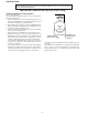
CD-C622/C2900 SPECIFICATIONS CD-C622/C2900 General Power source: Power consumption: (CD-C622) Power consumption: (CD-C2900) Dimensions: Weight: Amplifier section Output power: (CD-C622 Except for Canada) Output power: (CD-C622 For Canada) Output power: (CD-C2900 Except for Canada) Output power: (CD-C2900 For Canada) Output terminals: (CD-C622) Output terminals: (CD-C2900) Input terminal: Tuner section Frequency range: Compact disc player section Type: 3-disc multi-play compact disc player Signal read
CD-C622/C2900 NAMES OF PARTS CD-C622/C2900 3 4 5 1 2 6 7 8 9 10 11 12 13 14 Front Panel 1. Disc Number Selector Buttons 2. Disc Tray 3. Multi-function Indicator 4. Disc Skip Button 5. Open/Close Button 6. Extra Bass Indicator 7. FM Stereo Mode Indicator 8. FM Stereo Indicator 9. (CD) Repeat Indicator 10. (CD) Play Indicator 11. (CD) Pause Indicator 12. Spectrum Analyzer/ Volume Level Indicator 13. (TAPE 2) Racord INdicator 14. (CD) Disc Number Indicators 15. (CD/TUNER) Memory Indicator 16.
CD-C622/C2900 Front Speaker 1 CP-C622 1. Super Tweeter 2. Woofer 3. Bass Reflex Ducts 4. Speaker Wire 2 4 3 1 CP-C2900 1. Super Tweeter 2. Tweeter 3. Woofer 4. Bass Reflex Ducts 5. Speaker Wire 2 3 4 5 Rear Speaker (CD-C622 Only) GBOXS0021AWM1 1. Full Range Speaker 2. Speaker Wire 1 2 CD-C622/C2900 1 Remote Control 1. Remote Control Transmitter LED CD Control section 2. Disc Number Select Buttons 3. Memory Button 4. Pause Button 5. Clear Button 6. Track Down/Review Button 7.
–6– 9 8 7 6 5 4 3 2 AM 12:00 POWER MEMORY/ SET CLOCK AM 0:00 0:00 TUNING/ TIME ( ) In this example, the clock is set for the 12-hour (AM 12:00) system. (Main unit operation) SETTING THE CLOCK or ) button to adjust the hour. or ) button to adjust the The clock starts operating from "0" seconds. (Seconds are not displayed.) Press the MEMORY/SET button. Press the TUNING/TIME ( or ) button once to advance the time by 1 minute. Hold it down to change the time in 5 minute intervals.
FM/AM loop antenna x 1 Antena de cuadro de FM/AM x 1 –7– Black Negro Black Negro Front speaker (Left) Altavoz delantero (Izquierdo) Red Rojo Wire with the white line Cable con la línea blanca Rear speaker (Left) Altavoz trasero (Izquierdo) POWER POWER Turning the power on and off Conexión y desconexión de la alimentación Front speaker (Right) Altavoz delantero (Derecho) Red Rojo Wire with the white line Cable con la línea blanca Rear speaker (Right) Altavoz trasero (Derecho) Speaker connectio
–8– Black Negro Red Rojo Black Negro Red Rojo Front speaker (Left) Altavoz delantero (Izquierdo) POWER POWER Turning the power on and off Conexión y desconexión de la alimentación Front speaker (Right) Altavoz delantero (Derecho) Speaker connection Conexión de los altavoces 15 15 Remote Sensor Sensor remoto AC 120 V, 60 Hz 120 V de CA, 60 Hz 8” - 20’ (0.2m - 6m) 0,2m - 6m Batteries are not included. Las pilas no están incluidas.
CD-C622/C2900 DISASSEMBLY Caution on Disassembly Follow the below-mentioned notes when disassembling the unit and reassembling it, to keep it safe and ensure excellent performance: 1. Take cassette tape and compact disc out of the unit. 2. Be sure to remove the power supply plug from the wall outlet before starting to disassemble the unit. 3. Take off nylon bands or wire holders where they need be removed when disassembling the unit.
CD-C622/C2900 (E1)x1 ø3x10mm ( M1 ) x1 ø3 x10mm Front Panel (E2)x2 (E3)x1 (E5)x1 CD Servo PWB ( M2 ) x2 (E2)x2 (E4)x1 (G1)x1 ( M2 ) x2 CD Player Unit (E1)x2 ø3x8mm Figure 10-4 (F1)x1 ø3x8mm Main PWB ( N1 ) x4 ø3 x12mm Figure 10-1 ( P1 ) x1 ø2.
CD-C622/C2900 CP-C622 STEP 1 REMOVAL Front Speaker CP-C622 PROCEDURE FIGURE 1. Front Panel ............ (A1) x1 2. Tip .......................... (A2) x2 3. Screw ..................... (A3) x4 11-1 Front Panel (A1)x1 (A3)x4 ø4x12mm Piezo (A2)x2 Note: The rear speakers can be easily disassembled. Therefore the disassembling method is not discribed. For details refer to the disassembling drawing in the Parts Guide.
CD-C622/C2900 REMOVING AND REINSTALLING THE MAIN PARTS CD MECHANISM SECTION Perform steps 1, 2, 3, 13 and 14 of the disassembly method to remove the CD mechanism. Loading / Up / Down Motor How to remove the loading motor (See Fig. 12-1) Motor PWB 1. Remove the screws (A1) x 2 pcs., to remove the loading motor. ( A1 ) x2 ø2.6 x5mm Figure 12-1 How to remove the pickup (See Fig. 12-2) Stop Washer ( B1 ) x2 ( B3 ) x1 ø2.6 x6mm 1. Remove the screws (B1) x 2 pcs., to remove the shaft (B2). 2.
CD-C622/C2900 ADJUSTMENT • FM RF Signal generator: 1 kHz, 75 kHz dev., FM modulated MECHANISM SECTION • Driving Force Check Torque Meter Test Stage Frequency Frequency Display Specified Value Play: TW-2412 Tape 1: Over 80 g Tape 2: Over 80 g • Torque Check Torque Meter Specified Value Tape 1 Play: TW-2111 Tape 2 30 to 60 g. cm Fast forward: TW-2231 — 60 to 120 g.cm Rewind: TW-2231 — 60 to 120 g.cm Normal speed Adjusting Point Specified Value MTT-111 Volume in motor.
CD-C622/C2900 TEST MODE • Setting the test mode Any one of test mode can be set by pressing several keys as follows. + + TEST: CD operation test • TEST mode Function — CD test mode Setting of TEST mode Indication of CD TST mode (Fig. 14-1) IL is not performed. OPEN/CLOSE operation is manual operation. The pickup can be moved by using the ( LASER ON Tracking on the spot. SERVO OFF PLAY key input ) or ( ) key. Tracking on the spot.
CD-C622/C2900 NOTES ON SCHEMATIC DIAGRAM • Resistor: To differentiate the units of resistors, such symbol as K and M are used: the symbol K means 1000 ohm and the symbol M means 1000 kohm and the resistor without any symbol is ohm-type resistor. Besides, the one with “Fusible” is a fuse type. • Capacitor: To indicate the unit of capacitor, a symbol P is used: this symbol P means micro-micro-farad and the unit of the capacitor without such a symbol is microfarad.
CD-C622/C2900 WAVEFORMS OF CD CIRCUIT STOP FOCUS 1 2 PLAY SERCH 5ms 0.50 V IC1 20 F.E 5ms 5.0 V IC1 54 DRF 0.5ms 10.0 V JP+ 7 0.5ms 10.0 V JP- 8 0.5ms 0.50 V JP 9 0.5ms 1.00 V TE 3 1 3 6 PLAY CUE 0.5ms 1.00 V HF 4 0.5ms 5.0 V HFL 1 5 0.5ms 5.0 V TES 3 3 0.5ms 1.00 V HF NORMAL DISC TN0=01 10 20ms 1.00 V SPO 11 20ms 2.00 V CLV+ 2 REVIEW PLAY TCD-712 (140mm) TN0=01 4 5 0.5ms 5.0 V HFL 1 0.5ms 5.0 V TES 3 6 50ms 10.0 V JP+ 7 50ms 10.0 V JP- 8 50ms 0.
– 17 – Figure 17 BLOCK DIAGRAM (1/3) M M PICKUP IN SW4 M1 SPINDLE MOTOR M2 SLED MOTOR TRACKING COIL FOCUS COIL 15 16 26 27 6 7 4 5 23 1 2 3 4 20 25 8 ~ 14 21 22 29 ~ 35 IC3 M63001FP FOCUS/ TRACKING/ SPIN/SLED DRIVER 1 2 7 36 28 39 38 37 20 40 24 18 42 41 30 31 54 15 16 27 23 29 FIN2 FIN1 E F IC1 LA9241M SERVO AMP. 64 VCC1 62 LD0 TO FD SPO NC SLD 22 JP– 32 Q52 CV+ 40 SLC 43 SL1 44 ~ Q1 SL– SL+ DRF PU-IN SW +B5 +B1 SL+. SL–.
CD-C622/C2900 SWM3 FOOL PROOF SWM4 F.A.S SOLM1 SOLENOID AM LOOP FM ANTENNA ANTENNA L301 IC301 TA7358AP FM FRONT END 1 FM B.P.F FM IF 6 +B4 +B4 CF301 T301 SWM5 CAM 9 4 5 8 7 L302 T351 FM IF IN FM OSC FM RF VR351 MPX VCO ADJ AM IF T352 CF351 1 3 AM MIX 21 20 6 5 AM IF GND FM+B FM DET IC303 LA1805 FM/AM IF MPX.
CD-C622/C2900 SWM3 PROOF SWM4 F.A.
CD-C622/C2900 A C30 0.1/50 C31 220/6.3 C29 4.7/50 44 C27 0.001 R41 47K C18 0.47/50 C12 0.1 SLOF R40 5.6K R43 56K C24 2.2P 42 R38 470 HF TP1 C23 0.0027 40 39 38 37 TES 36 TOFF 35 TGL 34 JP+ SL+ JP– SL– R42 47K C25 R39 27P 1K 43 41 R44 33K C26 0.033 HFL SLD 29 30 31 32 33 6 C22 220P R36 220K C21 0.0033 R33 R32 1.2K 10K R34 3.3K VREF SLOF 5 REF SPO R29 56K FE– SPG R28 10K C16 0.0047 R23 10K C20 47/16 NC R19 1K 45 C19 1/50 S.Q.
CD-C622/C2900 R57 1K R58 1K R59 1K C49 100P(CH) C48 100P C47 100P(CH) C44 100P(CH) C46 100P (CH) R60 1K C38 0.01 C45 100P(CH) CD SIGNAL R61 1K R62 1K R63 1K +B +B C42 15P 24 25 26 27 28 29 30 31 CNP11 D82 1SS133 C74 220P TO MAIN PWB +B R66 220 R64 22 C75 0.001 C50 0.022 CD_LCH P24 1 - B CNS11 Q52 KTC3203 Y R55 +B C43 100 330/6.3 R65 1K L61 0.82µH +B 32 A_GND C73 220P 1 2 3 4 5 6 L-CH D-GND +7V +12V ZD61 MTZJ5.6B R74 100K R71 C71 R73 2.
CD-C622/C2900 VD303 C318 SCV211C 22P(CH) 2 TP301 R312 680 C338 100P C316 100P C393 1/50 Q302 2SC535 C OSC BUFF +B R380 1.5K C381 12P(CH) D305 1SS133 AM SIGNAL MAIN PWB-A1(1/3) G H • NOTES ON SCHEMATIC DIAGRAM can be found on page 15. 1 2 3 4 Figure 22 SCHEMATIC DIAGRAM (3/10) – 22 – 5 6 IC302 IO1 IF IN BO4 IO2 PD CL DI A IN NC VSS CE A OUT 1 2 3 4 5 6 7 8 9 10 11 R374 1K R373 1K R372 1K R371 1K D304 1SS133 X IN X OUT X352 4.
CD-C622/C2900 NC VCO R361 10K 0.015 R375 1.2K C357 3.3/50 FM/AM SWITCHING Q343 11 12 KRA109 M 3 8.4V 4.4V 2 1 5.1V C366 1/50 C365 1/50 C367 1/50 D342 1SS133 L343 100µH VR351 6.8K(B) VCO R362 390 R369 2.2K R350 47K C358 0.0015 R352 15K 13 AM /FM DET TUN OUT IND L CH MPX –IN R CH FM– M/ST C364 9 10 C363 0.015 2 1 CF351 3 +B 15 14 16 5 6 7 8 R356 10K C360 0.022 R365 680 C395 0.
CD-C622/C2900 A RECORD SIGNAL PLAYBACK SIGNAL FM SIGNAL R625 22K C629 22/25 R629 560(1/2W) 11 C112 330P 24 C114 330P 23 22 C154 47/16 C122 1/50 21 20 18 19 R121 100K C117 0.033 R119 56 0V 4 6 5 C113 330P 7 C121 1/50 R125 5.6K C119 560P R131 33K R135 622:5.6K 2900:8.2K H • NOTES ON SCHEMATIC DIAGRAM can be found on page 15. 3 4 Figure 24 SCHEMATIC DIAGRAM (5/10) – 24 – 5 8 6 R139 560 R117 1K C115 47/25 3 C129 470P 2 R137 6.8K C131 0.001 1 Hich= C128 3.
CD-C622/C2900 DIGITAL OUTPUT PWB-A6 CD SIGNAL P21 12 - D +B CNP99 TO CD SERVO PWB CNS99 D_OUT 1 1 3 3 +4.3V +B 2 2 2 L99 3 1 1 2.2µH CD GND IC99 C99 C98 100/10 0.022 BI99 +B R633 22K IC601 M62439SP AUDIO PROCESSOR +B 19 18 17 16 15 14 R608 R606 R604 R602 C612 C614 1.5K 1.5K 1.5K 1.5K 0.033 0.22 C602 4.7/50 C606 4.7/50 R640 47K R626 12 11 R629 560(1/2W) L-CH R634 22K JK601 VIDEO IN R-CH C630 0.022 TUN_R A_GND TUN_L R624 330 DO CE DI CL D_GND A_12V R638 220K C616 4.
CD-C622/C2900 + IC901 STK4074B POWER AMP Ch2 7 8 9 C902 220P R Q905 2SC3331 C917 47/50 D903 1SS133 15 47P D906 1SS133 D904 1SS133 Q907 2SC3331 C920 0.022 R918 820 Q904 2SC3331 R929 1K R925 0.1(1W) 3 C905 220P R903 100K A_GND R902 68K 2 C R926 0.1 (1W) C921 0.
CNP804 R960 22(1/2W) 2 2 1 1 R942 4.7K WTM801 R949 330(1/2W) C956 100/50 C936 C937 0.1 0.1 (ML) (ML) Q908 3 KRC107 M R936 R934 R937 4.7 4.7 56K C938 47/50 +B M901 FAN MOTOR HEADPHONES PWB-A5 1 2 3 4 5 +B JK970 HEADPHONES 5 FW801 8 7 6 5 4 3 2 1 D907 2 1SS133 1 M 1 C954 100/50 R938 56K Q906 2SC3331 R939 56K +B R941 4.
CD-C622/C2900 A DISPLAY PWB-A3 R721 100K R722 100K Q705 2SC3331 4 5 6 7 8 9 10 11 12 13 14 15 16 17 18 19 20 21 22 23 24 25 26 27 28 29 30 31 32 33 R723 100K Q707 2SC3331 Q706 2SC3331 P9 81 82 83 84 85 86 87 88 89 90 91 92 93 94 95 96 97 80 C702 1/50 R708 1K R707 1K C720 47/50 R706 1K G10 G09 G08 G07 G06 G05 G04 P22 P21 P20 P19 P18 P17 P16 P15 P14 P13 P12 P11 P10 P09 P08 P07 P06 P05 P04 P03 P02 P01 G11 1 2 3 P8 P7 P6 P5 P4 P3 P2 P1 P11 P10 G9 G8 G7 G6 G5 G4 B F F F FL701 FL DISPLAY 79
F F F 25 26 27 28 29 30 31 32 33 34 35 36 37 38 39 1 2 3 4 5 6 7 8 9 1 2 3 4 5 6 7 8 9 10 10 11 11 12 12 13 13 C706 1/50 C709 0.022 P1 P11 P10 G9 G8 G7 G6 G5 G4 G3 G2 G1 89 90 91 92 93 94 95 96 97 98 99 100 DO DI CE CLK LCK1 1 VDD +B 1 2 3 4 5 6 7 8 9 R778 R777 R776 R775 R774 C710 220/10 1K 1K 1K 1K 1K 14 R772 1K R771 1K 15 CD DSP RWC C707 IC701 RESET 10 15P IX0280AW X2 11 XL701 C708 TEM CONTROL X1 12 4.
CD-C622/C2900 CD-C622 A FC7 R374 R373 R372 R371 R939 R929 D904 C923 C369 ZD351 E C B RL901 Q904 D907 1 2 3 R830 R949 R946 R966 C910 C909 D801 Q908 H 3 C611 C826 C831 2 D906 R937 C937 C821 C918 E C B R942 D82 Q821 3 C830 C920 C917 C921 R941 R934 2 R620 R907 R922 C915 R931 C912 C936 1 R640 ZD602 R646 Q604 C626 R613 C621 R628 C625 R352 R913 R936 C938 G R605 R350 C364 C366 X352 R348 C353 R349 C911 C907 R928 R917 R918 C916 R916 C924 R921 R923 R924 Q907
CD-C622/C2900 P39 12 - D TO CD SERVO PWB CNP11 P35 8 - H TO DISPLAY PWB CNS701 CNS11 1 2 3 4 5 6 RD BL BL BL BL BL FC701 1 R164 E C B R115 R162 F805 2A/250V IC101 R155 P38 4 - D CNS101 TO TAPE MECHANISM TAPE1 HEAD R123 C119 R121 R125 R131 C127 C128 C131 C133 C139 R137 C129 C141 TO TAPE MECHANISM TAPE2 HEAD C117 R102 C111 C121 R139 R141 C135 R171 C155 R175 R157 C145 Q113 5 4 3 2 1 C102 Q107 R107 C105 R112 C142 WTM801 1 2 3 4 5 6 7 8 9 10 11 12 P38 5 - D CNS102 R135 R145 R134 C15
CD-C622/C2900 CD-C2900 A FC701 R374 R373 R372 R371 G R939 1 C937 R934 R925 C611 R620 C918 C C808 1 2 3 R830 R949 R946 D907 C910 C909 Q908 D801 H 2 R609 C369 Q904 R966 1 R640 ZD602 R646 Q604 C923 E C B RL901 C936 R929 D904 C826 C831 2 R937 R938 D906 C920 C917 E C B C821 R922 C915 C921 R941 R942 D820 Q821 3 2 C830 R930 R931 C912 C938 R926 R913 Q905 – C911 C907 R928 R917 R918 C916 R916 C924 R921 R923 R924 C904 R912 D903 R-CH C626 C960 IC901 D960 R
CD-C622/C2900 P39 12 - D TO CD SERVO PWB CNP11 P37 8 - H TO DISPLAY PWB CNS701 CNS11 1 2 3 4 5 6 RD BL BL BL BL BL FC701 1 R155 C102 Q107 R107 Q124 C151 L104 R168 C106 C150 C105 CNS102 TO TAPE MECHANISM TAPE2 HEAD P38 4 - D CNS101 TO TAPE MECHANISM TAPE1 HEAD C117 R102 C111 C121 R123 C119 R121 R125 R131 C127 C128 C131 C141 P38 5 - D C133 C139 R137 C129 R139 R141 C135 R171 R135 R145 R134 C154 C155 R175 C142 WTM801 R157 C145 5 4 3 2 1 F805 2A/250V 1 2 3 4 5 6 7 8 9 10 11 12 Q113
CD-C622/C2900 CD-C622 COLOR TABLE SWITCH PWB-A4 A RS707 B SW708 DISC SKIP RD09 LED705 RS711 LED706 LED707 RS706 IC703 SW709 OPEN/CLOSE 9 C719 C718 RS712 10 RS704 LED704 RS703 RS705 1 18 DISPLAY PWB-A3 39 38 37 RD28 SW729 EQUALIZER R721 R722 R708 R723 C709 ZD551 25 C707 C708 R744 R757 RD24 BI701 C705 BI703 1 R724 8 4 E C B R786 SW726 VOLUME DOWN B C E R760 R759 15 1 Q702 Q703 RD WH GY WH GY RD BL BL BL BL BL BL BL BL BL BL BL BL BL BL 1 2 3 4 5 6 7 8 9 10 11
CD-C622/C2900 COLOR TABLE R D (R ) RED LED703 LED704 RS703 YL OR LED702 BL VL GY WH ( W) BK PK BLUE VIOLET GRAY WHITE BLACK PINK GR ORANGE YELLOW GREEN RD07 704 BR BROWN SW707 DISC 3 LED701 RS701 SW706 DISC 2 SW705 DISC 1 FW702 RS702 1 8 RD06 RD05 25 24 23 22 21 20 19 18 17 16 15 14 13 12 11 10 9 8 7 6 5 4 SW704 TIMER/ SLEEP 3 2 1 LED722 70 R720 R736 R737 R739 R741 R740 R742 RD10 R733 R734 RD13 R745 R748 R747 RD12 R752 R753 R754 R751 R713 R712 SW716 TAPE R71
CD-C622/C2900 CD-C2900 COLOR TABLE SWITCH PWB-A4 A RS707 B SW708 DISC SKIP RD09 LED705 RS711 LED706 LED707 RS706 IC703 SW709 OPEN/CLOSE 9 C719 C718 RS712 10 RS704 LED704 RS703 RS705 1 18 DISPLAY PWB-A3 39 38 37 RD28 SW729 EQUALIZER R721 R722 R708 R723 C709 Q707 ZD551 25 BI701 C705 BI703 R760 Q702 1 R724 8 4 E C B R786 SW726 VOLUME DOWN B C E 1 2 3 4 5 6 7 8 9 10 11 1213 14 15 RD WH GY WH GY RD BL BL BL BL BL BL BL BL BL BL BL BL BL BL CNS806 WH GY WH G 12 11 1
CD-C622/C2900 COLOR TABLE R D (R ) BROWN RED LED703 LED704 RS703 RD07 704 BR YL OR ORANGE YELLOW GREEN LED702 BL GR BLUE VIOLET WH ( W) BK PK WHITE BLACK PINK GRAY SW707 DISC 3 LED701 RS701 GY VL SW706 DISC 2 SW705 DISC 1 FW702 RS702 1 8 RD06 RD05 25 24 23 22 21 20 19 18 17 16 15 14 13 12 11 10 9 8 7 6 5 4 SW704 TIMER/ SLEEP 3 2 1 LED722 70 R720 R736 R737 R739 R741 R740 R742 RD10 R733 R734 RD13 R745 R748 R747 RD12 R752 R753 R754 R751 R713 R712 SW716 TAPE R
CD-C622/C2900 SWM3 F. P. A FWM2 FWM1 PHM1 4 3 BK WH BK WH SOLM1 SOLENOID (254-8) + TAPE MECHANISM PWB-E B TO DISPLAY PWB CNSM1 P34 5 - H, P36 5 - H SWM4 F. A.
R93 50 1 CNP12 2 CNS12 11 L61 R91 R89 R35 R36 C29 R71 R90 R73 C22 C30 6 7 8 9 C73 R88 C24 15 14 13 12 11 10 R54 R55 2 C50 C74 R74 17 C28 D1 C72 R65 20 16 3 32 15 C23 C57 30 10 R43 R40 R39 R41 C56 R44 C25 33 25 R52 R38 R42 4 5 1 35 BI1B IC2 C40 C26 R72 60 P34 3 - H, P36 3 - H TO DISPLAY PWB 40 64 1 R53 R50 5 55 R51 C27 4 45 C39 3 C43 R63 C48 D81 48 C83 C41 C42 C44 C49 C45 R58 XL1 49 D82 R60 C38 C46 C47 R59 R57 C37 R47 R6
CD-C622/C2900 CD-C2900 A P33 10 - E TO MAIN PWB CNP802 B COLOR TABLE BR RD BL RD YL YL BR BK BR 1 2 3 4 5 6 7 8 CNS802 C T801 POWER TRANSFORMER BL RD BROWN RD(R) RED OR ORANGE YL YELLOW GR GREEN BL BLUE VL VIOLET GY GRAY WH ( W) WHITE BK BLACK PK PINK D Q802 3 2 1 3 2 1 C814 F 1 2 1 CNP801 2 CNS801 C801 RL801 C815 T802 POWER TRANSFORMER Q803 CNP806 1 2 3 4 E R808 D815 D818 D802 P36 2 - H TO DISPLAY PWB CNS806 D816 SO801 C810 AC POWER INPUT AC120 60Hz D8
CD-C622/C2900 VOLTAGE IC1 PIN VOLTAGE NO. 1 2.5V 2 2.5V 3 2.5V 4 2.5V 5 2.5V 6 2.5V 7 2.5V 8 2.5V 9 2.5V 10 2.5V 11 2.5V 12 2.5V 13 2.5V 14 2.5V 15 2.5V 16 2.5V 17 2.5V 18 2.5V 19 2.5V 20 2.5V 21 2.5V 22 0V 23 2.5V 24 2.5V 25 2.5V 26 2.5V 27 2.5V 28 2.5V 29 2.5V 30 2.3V 31 2.3V 32 0V 33 0V 34 5.0V 35 5.0V 36 0V 37 0V 38 5.0V 39 0V 40 0V 41 1.6V 42 2.4V 43 2.4V 44 2.4V 45 0V 46 2.5V 47 2.5V 48 0V 49 0V 50 2.4V 51 4.6V 52 4.6V 53 0V 54 0V 55 5.0V 56 5.0V 57 2.5V 58 2.5V 59 1.0V 60 1.0V 61 2.2V 62 4.
CD-C622/C2900 TROUBLESHOOTING (CD SECTION) When the CD does not function When the CD section does not operate When the objective lens of the optical pickup is dirty,this section may not operate.Clean the objective lens,and check the playback operation.When this section does not operate even after the above step is taken,check the following items. Remove the cabinet and follow the troubleshooting instructions.
CD-C622/C2900 • When the turntable fails to stop. 5V Is from 2.5V 5 V till 2.5V down pulse (approx. 300 ms) 0V No input into the IC701 pin 21 when the turntable is rotating? Check the SWM3 and the wiring from the IC701 pin 21 to the SWM3. Yes Is there following voltage input on the IC701 pin 21 in the specific state? When the CD mechanism is moved up: 0V In other states: 4.3V No Check the MECHA UP SW and the wiring from the IC701 pin 21 to the MECHA UP SW.
CD-C622/C2900 • When the CD tray fails to open or close. Is there following voltage input in specific state of IC701 pin 19? Open state: 0V Close state: 0V Intermediate state between open state and close state: 4.3V Check the OPEN CLOSE SW and the wiring from the IC701 pin 19 to the OPEN CLOSE SW. No Yes Is H output to IC2 pin 24 or 25 for 7 seconds when the OPEN/ CLOSE key is pressed?IC91 is defective. Replace it. Check the wiring of the IC2 pins 24 and 25, IC91 pins 1 and 3. No OK IC2 defective.
CD-C622/C2900 • Playback can only be performed when a disc is loaded. Is the Focus servo active? (Can you hear it working?) No Check the laser diode driver. Check the area around IC1(16) - (21) (focus servo circuit). No If the disc is not turning, the DRF should not change to "H". Yes Yes Does the DRF signal change from "L" to "H"? Check the spin system. Yes Yes No Is HF waveform normal (see the Fig.45-1, 2)? Check the periphery of IC1 pins 41 and 42. Level is abnormal.
CD-C622/C2900 • Checking the spin system. Play operation is performed without disc. Yes Yes The turntable rotates a little. The spin driver circuit is normal. No Yes The turntable fails to rotate or rotates at high speed. Check the periphery of IC1 pins 23 to 27, pin 39, and pin 40, IC2 pin 12 and pin 13, IC5 to CNP3. • Checking the VCO-PLL system Play operation is performed when disc exits. Yes Although HF waveform is normal, TOC data cannot be read. Yes Check PDO waveform (Fig. 46).
CD-C622/C2900 FUNCTION TABLE OF IC IC1 VHiLA9241M/-1: Servo Amp. (LA9241M) (1/2) Pin No. Function Port Name 1 FIN2 Connection pin for photodiode of pickup. RF signal is generated through addition with FIN pin, and FE signal is generated through subtraction. 2 FIN1 Connection pin for photodiode of pickup. 3 E Connection pin for photodiode of pickup. TE signal is generated through subtraction with F pin. 4 F Connection pin for photodiode of pickup.
CD-C622/C2900 IC1 VHiLA9241M/-1:Servo Amp.(LA9241M) (2/2) Pin No. Function Port Name 51 CL Micro computer command clock input pin. 52 DAT Micro computer command data input pin. 53 CE Micro computer command chip enable input pin. 54 DRF (DETECT RF) RF level detection output. 55 FSS (Focus Serch Select) Pin to switch focus search mode. (± search/+ search for reference voltage) 56 VCC2 VCC pin for servo system and digital system. 57 REFI Pin to connect pass control for reference voltage.
CD-C622/C2900 IC2 VHiLC78622N-1: Servo/Signal Control (LC78622NE) (1/2) Pin No. Terminal Name Input/Output Function 1 DEFI Input Defect detection signal (DFF) input terminal. (When this terminal is not used, connect it to 0V.) 2 TAI Input For PLL Input terminal for test. Pull-down resistor built in. Be sure to connect this terminal to 0V.
CD-C622/C2900 IC2 VHiLC78622N-1: Servo/Signal Control (LC78622NE) (2/2) Pin No. Terminal Name Input/Output Function 47* SBSY Output Sub-code clock sync signal output terminal. 48* EFLG Output C1, C2, single, double correction monitor terminal. 49* PW Output Sub-code P, Q, R, S, T, U, and W output terminal. 50* SFSY Output Sub-code frame sync signal output terminal. Falling occurs when the sub-code is in standby state. Input Sub-code read clock input terminal.
CD-C622/C2900 IC3 VHiM63001FP-1: Focus/Tracking/Spin/Slide Driver (M63001FP) 1 2 3 4 5 6 7 8-14 15 16 17 18 19 20 21 22 23 24 25 26 27 28 29-35 36 37 38 39 40 41 42 Terminal Name Function IN2IN1AIN1BOUT1OUT1+ OUT2OUT2+ GND OUT3+ OUT3IN3VCC1 STANDBY VRFE MUTE IN5IN5+ VCC2 IN4OUT4OUT4+ VCC3 GND OUT5+ OUT5OUT6+ OUT6VCC4 IN6IN6+ CH2 inverted input. CH1 inverted input. CH1 output offset control. CH1 inverted output. CH1 non-inverted output. CH2 inverted output. CH2 non-inverted output.
CD-C622/C2900 IC701 RH-iX0280AWZZ:System Microcomputer (IX0280AW) (1/2) Pin No.
CD-C622/C2900 IC701 RH-iX0280AWZZ:System Microcomputer (IX0280AW) (2/2) Pin No.
CD-C622/C2900 FL701 VVKBJ685GNK-1: FL Display 11G 9G 10G SI S1 S5 S4 S3 S2 CO Dp B7 B6 B5 B4 B3 B1 B1 B2 1G 2G 3G 4G 5G 6G 7G 8G a h B7 B8 B9 B10 B11 B12 B13 B14 B21 B20 B19 B18 B17 B16 B15 j f B6 B5 b k g m n r B4 B3 B2 e p c d B1 [ 1G~8G ] [ 10G ] ANODE CONNECTION 1G 2G~6G 7G 8G 9G 10G 11G P1 Dp Dp Dp Dp S1 S1 S1 P2 d d d d B1 B1 B1 P3 c c c c B2 B2 B2 P4 n n n n B3 B3 B3 P5 p p p p B4 B4 B4 P6 r r r r B5 B5 B5 P
CD-C622/C2900 PARTS GUIDE CD-C622 MODEL CD-C622 mini component system consisting of CD-C622 mini component system, CP-C622 and rear (GBOXS0021AWM1) speaker system. CD-C2900 CD-C2900 mini component system consisting of CD-C2900 mini component system and CP-C2900 speaker system. “HOW TO ORDER REPLACEMENT PARTS” To have your order filled promptly and correctly, please furnish the following information. 1. MODEL NUMBER 2. REF. No. 3. PART NO. 4. DESCRIPTION For U.S.A.
CD-C622/C2900 NO. PRICE RANK PARTS CODE DESCRIPTION CD-C622/C2900 INTEGRATED CIRCUITS IC1 IC2 VHILA9241M/-1 VHILC78622N-1 J J IC3 VHIM63001FP-1 J IC101 VHIAN7345K/-1 J IC301 IC302 IC303 IC562,563 IC601 IC701 VHITA7358AP-1 VHILC72131/-1 VHILA1805//-1 VHIKIA4558P-1 VHIM62439SP-1 RH-IX0280AWZZ J J J J J J IC703 IC704 IC901 VHIBU2092F/-1 VHIKIA7042AP1 VHISTK4074B-1 J J J AS Servo Amp.
CD-C622/C2900 NO.
CD-C622/C2900 NO.
CD-C622/C2900 NO.
CD-C622/C2900 NO.
CD-C622/C2900 NO.
CD-C622/C2900 NO. PRICE RANK PARTS CODE DESCRIPTION NO.
CD-C622/C2900 CD-C622/C2900 306-2 A 306 306-1 701 306-3 B 304 701 302 704 C 702 702 301 D 303 703x2 703x2 E M1 F 305 M2 305x2 G SW4 H PWB-C 1 2 3 4 Figure 8 CD MECHANISM EXPLODED VIEW 8 –– –– 63 5 6
CD-C622/C2900 CD-C622/C2900 622 249 249-1 A 203 602x10 604x2 PWB-A4 602 2900 203 239 PWB-A3 B 604x10 215 249-2 602x2 FL701 244 C 227 PWB-A5 244-7 244-8 244-6 244-14 604 253 240x6 605x2 244-18 244-16 244-4 244-19 IC901 244-20 606x2 244-17 244-15 D PWB-A6 244-5 244-13 244-11 PWB-A1 608 Silicon grease 244-22 Q823 Q824 244-12 244-10 209 244-21 241 606x3 Silicon grease Q822 PWB-E 244-9 244-3 604x5 E 247 212 244-1 204(204-1, 204-2, 204-3, 204-4, 204-5, 204-6, 204-7, 2
CD-C622/C2900 CD-C622/C2900 256 620 255 A 255-3 255-2 617x2 255-1 621 202 237 B 219 SW3 236 C 236 221 236 251-3 617x2 251-2 251-1 251 251-4 D 201 603 223 CD MECHANISM 607 E 610 229 213 611 207 236x2 616 226 214 230 217 231 236 231 228 601 F 607 235 234 254 216 218 SW2 213 238 232 G 609x2 236 210 611 211 M3 222 612x4 PWB-B H 611 1 PWB-D 236 2 3 4 Figure 10 CABINET EXPLODED VIEW (2/2) 65 – –– 10 – SOLM2 5 6
CD-C622/C2900 CP-C622 A 907x4 SP3,4 909 903 B C 904 SP1,2 908 D 902 908 PIEZO SP3,4 E 905 901 BK RD 906 BK RD F PIEZO SP3(L-CH) SP4(R-CH) G WOOFER SP1(L-CH) SP2(R-CH) WOOFER SP1,2 H 1 2 3 4 Figure 11 SPEAKER EXPLODED VIEW (1/3) 66 –– –– 11 5 6
CD-C622/C2900 CP-C2900 TWEETER SP3(L-CH) SP4(R-CH) A C1,2 Capacitor SP5,6 902,903 RED B SUPER TWEETER SP5(L-CH) SP6(R-CH) BK YE BK RED 909x2 WOOFER SP3(L-CH) SP4(R-CH) BK 906 904,905 908x2 (with Capacitor C1,2) C 912 D 908x2 SP3,4 E 909x2 907 SP1,2 F 911x4 901 G SUPER TWEETER SP5(L-CH) SP6(R-CH) 910 TWEETER SP3(L-CH) SP4(R-CH) H C1,2 Capacitor 2.2µF,50V, Electrolytic (N.P.
CD-C622/C2900 GBOXS0021AWM1 (CD-C622 ONLY) 904x6 A 905 SP1,2 B 903 C 901 902 SP1,2 D E F G H 1 2 3 4 Figure 13 SPEAKER EXPLODED VIEW (3/3) 68 –– –– 13 5 6
CD-C622/C2900 PACKING OFF THE SET (For U.S.A. Only) CP-C622 Setting position of switches and knobs Tape Mechanism STOP Front Speaker(L/R) UNIT CP-C622 92L411-0108 Polyethylene Bag SPAKP0013AWZZ1 Polyethylene bag SPAKA0203AWZZ Packing Add.,(Left/Right) Bottom 92L412-0125 Packing Add., (Top/Bottom) 92L416-0060 Center Pad B A Rear Speaker(L/R) GBOXS0021AWM1 FM/AM Loop Antenna Quick Guide Operation Manual AC Power Cord Remote Control 92L16-01-0002 Polyethylene Bag 92LBAG1460C1 Polyethylene Bag.
CD-C622/C2900 CP-C2900 Setting position of switches and knobs Tape Mechanism STOP Front Speaker (L/R) UNIT CP-C2900 92L70032001600 Polyethylene Bag SPAKP0013AWZZ1 Polyethylene bag 92L71525003200 Sheet SPAKA0211AWZZ Packing Add.,(Left/Right) Bottom 92L720TPC46200 Packing Add.,(Top) 92L720BPC46200 Packing Add.,(Bottom) A FM/AM Loop Antenna Quick Guide Operation Manual AC Power Cord Remote Control 92LBAG1460C1 Polyethylene Bag.
CD-C622/C2900 —MEMO— –– 16 71 ––
CD-C622/C2900 COPYRIGHT © 1999 BY SHARP CORPORATION ALL RIGHTS RESERVED. No part of this publication may be reproduced, stored in a retrieval system, or transmitted in any form or by any means, electronic, mechanical, photocopying, recording, or otherwise, without prior written permission of the publisher.