
Technical data


Rev.February 1996 Conti-Dryer Page 23
CD 25-600
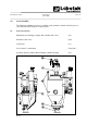
5.2 Assembly of accessories
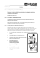
5.2.1 Assembly of mounting base (26)(see fi g. R1637 section 5.1)
The mounting base, featuring a sight glass and a magnet grid, is fi tted to avoid magnetic
particles in the raw material from entering the screw of the production machine, or when it
is required to add masterbatch or other additives.
The mounting base is as standard equipped with a manually operated slide valve. A
pneumatic one is also available.
1. Close slide valve and disassemble CD from
frame / processing machine.
2. First assemble intermediate fl ange / slide valve
(24a) on the machine.
3. Then fi t mounting base (26) on intermediate
fl ange / slide valve (24a).
4. Assemble CD on frame / processing machine.
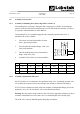
R1693
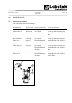
DDL 25 DDL 50 DDL 90 DDL 180 DDL 350 DDL 500 DDL 600
H 45 45 60 60 120 120 120
I 60 60 80 80 118 118 118
J 120 120 182 182 236 236 236
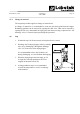
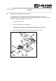
5.2.2 Assembly of pneumatic slide valve
On CD 350-600 it is recommened to fi t a pneumatic slide valve. A manually operated valve
can be diffi cult to operate on these unit owing to the amount of material in the hopper.
If CD 25-180 is assembled on frame, then fi rst assemble an intermediate fl ange prior to the
pneumatic valve. On CD 350-600 the valve can be fi tted immediately.
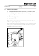
Warning: Do not connect compressed air to the valve before appropiate measures are taken
to hinder unintended access to the slide valve, so eliminating the risk of bodily injury.
The slide valve is factory-labelled against sharp edge mechanism.