
Service manual
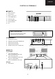

3
32JW-73E
ELECTRICAL SPECIFICATIONS
•White Level
Set brightness control to get total picture tube cathode current of 600 µA under no signal condition.
Maximum necessary correction of each picture tube cathode current to get 8550 degrees K+1 MPCD
screen temperature should not exceed 15% of its original value.
X=0.290 ± 0.015 Y=0.300 ± 0.015
WARNING
The chassis in this receiver is partially hot. Use an isolation transformer between the line cord plug
and power receptacle, when servicing this chassis.
To prevent electric shock, do not remove cover. No user-serviceable parts inside. Refer servicing to
qualified service personnel.
Specifications are subject to change without prior notice.
•Power Input .................... 220V-240 Volts AC 50Hz
•Power Consumption
Normal Operation (Method IEC60107) ............ 85W
Stand-by Operation ............................................ 3W
•Audio Power Output Rating (MPO) / Impedance
Internal Left Speaker ................................. 10W, 7Ω
Internal Right Speaker .............................. 10W, 7Ω
•Speakers
Left / Right ................................................. 12 x 6cm
•Convergence (Maximum Misconvergence)
Static (Centre) between any two colours ... 0.08 cm
Dynamic after static equals zero
Within 10cm (4”) circle ....................... 0.12cm
10-25cm (4-10” ) circle ...................... 0.20 cm
Everywhere else ................................ 0.28 cm
•Focus ................................. High Bi-Potential Electrostatic
•Sweep Deflection ................................................ Magnetic
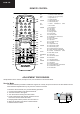
MODEL DESTINATION (Operation Manual languages).
32JW-73E: Deutsch, Français, Nederlands.
32JW-73EES: Español, Português.
32JW-73ESE: Dansk, English, Norsk, Suomi, Svenska.
•Picture Intermediate frequency
L’ ................................................ 33.9MHz
L, B/G, D/K,I .............................. 38.9MHz
•Sound Carrier Trap
L’ ................................................ 40.4MHz
L, D/K ......................................... 32.4MHz
B/G ............................................ 33.4MHz
I .................................................. 32.9MHz
•Adjacent Sound Carrier Trap
L’ ................................................ 32.4MHz
L, D/K, B/G ................................ 40.4MHz
I .................................................. 40.9MHz
•Adjacent Picture Carrier Trap
L’ ................................................ 41.9MHz
L, D/K, ........................................ 30.9MHz
B/G ............................................ 31.9MHz
•Aerial Input Impedance
VHF/UHF ................. 75 ohm Unbalanced
•Tuning Ranges ..... 45.75MHz thru 855.25 MHz
VHF: IR A - J / S1 - S41 CH (Hiperband)
UHF: I21 - I69 CH
CATV Special Channels