
Users Manual
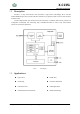
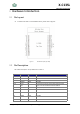
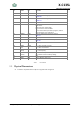
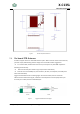
Table Of Contents
- 1 Module Overview
- 1.1 Features
- 1.2 Description
- 1.3 Applications
- CONTENTS
- LIST OF FIGURES
- HISTORY
- 2 Hardware Introduction
- 2.1 Pin Layout
- 2.2 Pin Description
- 2.3 Physical Dimensions
- 2.4 On-board Chip Antenna
- 2.5 Ordering Information
- 3 Electrical Characteristics
- 3.1 Absolute Maximum Ratings
- 3.2 Recommended Operating Conditions
- 3.3 ESD
- 3.4 WiFi/BLE RF Standards
- 4 Peripheral Schematics
- 5 Product Handling
- 5.1 Reflow Profile
- 5.2 Storage Conditions
- 5.3 Device Handling Instruction (Module IC SMT Prepara
- 6 Contact Information

X-C13SL
802.11bgn and BLE SoC
Shanghai ChipFresh Internet of Things Technology Co., Ltd
9
Table1. Pins Definition
2.3
Physical Dimensions
X-C13SL-1 Physical Dimensions (Unit: mm),please refer to Figure 3:
15
GPIO2
I/O
SPI,PWM
16
N,C
19
GPIO11
I
3.3V TTL UART1 Debug Input
DEBUG-RX
21
GPIO17
O
3.3V TTL UART1 Debug Output
DEBUG-TX
22,23
-
-
Null
24
GPIO8
IPD
Internal 10K pull-down resistor,
Boot select:
Low: boot from module flash.
High: boot from external UART.
This is used for factory firmware program, leave it
unconnected for user application
25
GPIO16
O,PU
3.3V TTL UART0 Communication Output
UART-TX
26
GPIO14
IPU/O
SPI,DAC,ADC
27
GPIO7
I
3.3V TTL UART0 Communication Input
UART-RX
28
GPIO12
I/O
SPI,PWM,ADC
29
GPIO5
Link
IPU/O
“0” – Wi-Fi connect to router
“1” – Wi-Fi unconncted
30
GPIO4
Ready
O
“0” – Boot-up OK;
“1” – Boot-up Fail;
31
GPIO3
Factory
IPU
press this button ( “Low” > 4s ) and loose to make
the module recover to factory setting.
32
N,C
33
RESET
I,PU
“Low” effective reset input.