HiPER 811 Quick Guide 2009-3-17 Version: 1.
Copyright Notice Copyright © 2000-2009, Shanghai UTT Technologies Co., Ltd. All rights reserved. The information of this publication is protected by copyright. No part of this publication may be reproduced, transmitted, transcribed, stored in a retrieval system, or translated into any language without written permission from the copyright holders. The scope of delivery and other details are subject to change without prior notice. Trademark UTT® is a registered trademark of Shanghai UTT Technologies Co.
Warning This equipment has been tested and found to comply with the limits for a Class B digital device, pursuant to part 15 of the FCC Rules. These limits are designed to provide reasonable protection against harmful interference in a residential installation. This equipment generates, uses and can radiate radio frequency energy and, if not installed and used in accordance with the instructions, may cause harmful interference to radio communications.
Table of Contents About This Guide ................................................................................................................. 1 0.1 Conventions ............................................................................................ 1 0.1.1 Conventions for page path ..................................................................... 1 0.1.2 Common Button ...................................................................................... 1 0.1.3 List ...................
3.3.6 3.4 How to Delete the Connection .............................................................. 28 Network Security................................................................................... 29 3.4.1 Virus Defense ....................................................................................... 29 3.4.2 Rate Limit .............................................................................................. 30 3.5 ARP Spoofing Defense ..............................................
About This Guide Note For best use of our product, it is strongly recommended that you update Windows Internet Explorer browser to 6.0 or above. 0.1 Conventions 0.1.1 Conventions for page path Lever one menu > lever two menu(bold)means the menu path to open some configuration page. E.g. System admin > Time means that in web interface, first click level one menu system admin, then click level two menu Time to open clock management page. 0.1.
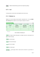
: Delete the selected entry(s) with the corresponding settings. 0.1.3 List In web page there are two kinds of lists: Editable list and read-only list. 0.1.3.1 Editable List Editable list is used to display, edit and delete configuration item. Let us take DHCP Static Binding List (see Table 0-1) as an example to explain the functions. Table 0-1 DHCP Static Binding List : Current page number/ total pages, the example means the current page is first page, and total one page. : Go to the first page.
jump to that page. : Enter the search text in text field, then type to display all the matched entries, besides, you can search within results. After search, if you want to display all the entries, you only need type in empty text field. Note: The match criterion is that search text exists in entry’s information. : Created entry number / maximum number, the example means two DHCP static binding entries have been set up and the maximum configurable entries number is 53.
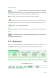
: Current status entry number /maximum number,the example means there are two status information entry in the list. : Refresh the list to view current status of the list. 0.1.3.3 Sorting Function Except Access Rule List in Advanced Setup > Access Rule page, all the lists in web page support sorting function. Steps are as following: Clicking the column title in list will make the list sorts the data by clicked column. The first click makes it sorted descendingly.
Chapter 1 Product Overview The HiPER 811 security gateway/VPN firewall is a purpose-built security system designed for small-sized businesses and enterprise branch offices. The HiPER 811 integrates a rich suite of functions, including L2TP/PPTP/IPSec VPN, NAT/PAT, firewall, bandwidth management, DHCP server/client, popular attack defense capability, system management and monitor, and so on. 1.
Messenger P2P (peer-to-peer) control: block or allow P2P application, e.g.
IPSec features as followed: 1. AutoIKE based on preshared key and manual key tunnels 2. ESP and AH protocols 3. DES, 3DES and AES 128/192/256 encryption algorithm 4. MD5 and SHA-1 hash algorithm 5. Diffie-Hellman group 1, 2 and 5 6. Main mode and aggressive mode 7. DPD (dead peer detection) and Anti-Replay 8. Hub-spoke and mesh connections 1.2 Specifications Conforms to IEEE 802.3 Ethernet and IEEE 802.
Chapter 2 Physical Installation This section describes how to install the Device. 2.1 Front Panel The LEDs and network ports are located on the front panel of the Device. Figure 2-1 Front Panel 2.1.1 LEDs The LEDs give real-time information of system status. The following table provides description of the LEDs status and their meaning. LED Status Description Green The Device is powered on. Off The Device is powered off.
Blinking Network activity on the Device. Off No activity on the Device. Blinking The Device is not operating correctly. Off The Device is operating correctly. Green Valid link on the associated port. Blinking Network activity on the associated port. Off No link established on the associated port. Green The associated port is connected at 100Mbps. Off The associated port is connected at 10Mbps. TRF FLT Link/Act 100M Table2-1 LEDs Description 2.1.
1. The reset operation will clear all the settings and preferences that you have configured. 2. You can also reset the Device to the factory defaults on the System Admin > Backup & Restore page.
2.2 Connecting the Device Before you install the Device, please make sure your PC can connect to the Internet through your broadband service successfully. If there is any problem, please contact with your ISP for help. After that, please install the Device according to the following steps. Don’t forget to pull out the power plug and keep your hands dry. Step 1 Power off your PC(s), Cable/DSL modem, and the Device.
Chapter 3 Quick Setup Guide After you have connected the Device into your network, you may configure it. This chapter describes how to configure the basic functions of your Device. It will only take you a few minutes. You can access the Internet via the Device immediately after it has been successfully configured. 3.1 Configure PC Before set up the Device, you need to install and configure TCP/IP properties on each network PC. Step 1 Connect the PC to the Device’s LAN port.
If the displayed page is similar to the screenshot below, it means that your PC has not connected to the Device. If it is failed to connect, please check it follow the steps below: 1. Is the connection between your PC and the Route correct? The LEDs of LAN port which links to the device and the LED on your PC’s adapter should be lit. 2. Is the TCP/IP configuration for your PC correct? If the Device’s IP address is 192.168.16.1, your PC’s IP address should be within the range from 192.168.16.
3.2 Login the Device Once your PC is properly configured, please do the following to use the Web-based Utility. For local access of the Device’s web-based utility, launch your web browser, and enter the Device’s default IP address: 192.168.16.1, in the RUL filed (see Figure 3-1). Then press the Enter key. Figure 3-1 Address Bar A login screen prompts you for your User name and Password. Enter Default (case sensitive) in the User name field, and keep the Password field empty (see Figure 3-2).
The first screen that appears is the Homepage (see Figure 3-3).
Figure 3-4 A Dialog Box Please click OK, then you can do common settings through the Start menu (see Figure 3-5), which including: Internet Connection, Network Security, Port Forwarding Rule, ARP Spoofing Defense, User Personal Policy, User Group Policy, Firewall Policy and System Info.
3.3 Internet Connection Click Start > Internet Connection,it will jump to Basic Setup > Internet Connection page. This page lets you setup the Internet Connection, view its status, and modify or delete it. Note 1. When you have finished the Internet connection setup, it is strongly recommended that you go to Start > Network Security page to do essential security settings. 2.
and then select PPPoE; Static IP: If you are required to use a permanent IP address, select Static IP; DHCP: If your ISP automatically assigns an IP address, select DHCP. Most cable modem subscribers use this connection type. ① Click Default ② Select Type Figure 3-6 Select Connection Type Depending on which connection type you select, you will see various settings. We will describe the settings for each connection type respectively (see chapter 3.3.1.1, 3.3.1.2 and 3.3.1.3).
3.3.1.1 PPPoE Connection If you choose PPPoE connection type, you will see the following page. Figure 3-7 PPPoE Connection Setup User Name and Password: Enter the PPPoE login user name and password provided by your ISP.
PPP Authentication: Select PPP authentication mode from this drop-down box, available options: NONE, PAP, CHAP and Either. PAP: Password Authentication Protocol; CHAP: Challenge Handshake Authentication Protocol; None: It means that there is no protocol will be used. Either: It means that the Device will automatically negotiate it with the peer device. LAN IP Address: Enter the IP address for the Device’s LAN interface.
Dial Schedule: If you select a schedule (set up on User Admin > Schedule Settings page), it will allow your Device to dial-up only in the selected schedule range. Else, the Device always can dial-up. Online Schedule: If you select a schedule rule (set up on User Admin > Schedule Settings page), your Device can keep the Internet connection active only in the online schedule range. Else, the connection always can keep active.
3.3.1.2 Static IP Connection If you choose Static IP connection type, you will see the following page. Figure 3-8 Static IP Connection Setup LAN IP Address: Enter the IP address for the Device’s LAN interface. LAN Subnet Mask: Enter the subnet mask for the Device’s LAN interface. WAN IP Address: Enter the IP address for the Device’s WAN interface, which is provided by your ISP. WAN Subnet Mask: Enter the subnet mask for the Device’s WAN interface, which is provided by your ISP.
3.3.1.3 DHCP Connection If you choose DHCP connection type, you will see the following page. Figure 3-9 DHCP Connection Setup LAN IP Address: Enter the IP address for the Device’s LAN interface. LAN Subnet Mask: Enter the subnet mask for the Device’s LAN interface. WAN MAC Address: This field displays the current MAC address of the WAN interface. In most cases, you need not change it. But when using DHCP connection type, your ISP may only allow one MAC address to be registered.
3.3.2 Internet Connection List When you have configured the Default connection, you can view its status in the Internet Connection List (see Table 3-1). To view current status of the connection, click Refresh button. Table 3-1 Internet Connection List Table 3-1 Internet Connection List (continued) Name: It displays the connection’s name. Interface: It displays the name of the physical interface to which the connection is bound. Connection Type: It displays the connection’s type.
1. PPPoE Connection Status There are eight kinds of status for PPPoE connection (see Table 3-2). During it is in connected status, it will also display the elapsed time (day: hour: minute: second) since connected. Status Description Closed The physical interface is inactive, or not dial-up. Dialing Start dialing up, but not receive response yet. Authenticating Server responded and is authenticating. Connected Authenticated succeed, and the connection is established and ready for date transmit.
Status Closed Description The physical interface is inactive, or the connection has release the IP address but not request a new one yet. Connecting Requesting an IP address. Connected Have acquired an IP address, the connection is established. Internal Error Undefined status. Table 3-4 Description of Connection Status – DHCP NAT Status: It displays whether the connection enable NAT function or not. The system will automatically enable NAT function during connection setup.
Click Refresh button to view current status of the connection. Table 3-5 Internet Connection List - PPPoE Connection 3.3.4 How to Renew and Release a DHCP Connection If your connection type is DHCP, when you click the Default hyperlink of the connection entry, the Renew, Release and Refresh buttons will show below the list (see Table 3-6). Click Renew button to re-acquire an IP address from the ISP’s DHCP server. Click Release button to release the IP address obtained from the ISP’s DHCP server.
3.3.5 How to Edit the Connection If you want to edit the connection, do the following: Step 1 In the Internet Connection List, click the Default hyperlink of the connection entry, the related information will display in the setup fields. Step 2 Modify the connection settings. Step 3 Click Apply button to save and apply your settings. 3.3.
3.4 Network Security On the Start > Network Security page, you can do essential security settings: virus defense and rate limit. You can’t go to this page if the Internet connection hasn’t been configured yet. Note When you click Apply button to save and apply your settings, the system will automatically enable the Synchronize with SNTP Server function (you also can setup it in System Admin >Time page), so it will acquire standard time once connected to Internet. 3.4.
Enable Popular Virus Defense: Select this check box to protect the device against popular virus attack, e.g., Worm.Blaster and Worm.Sasser. And it will discard those TCP packets whose destination port is 135, 136, 137, 138, 139, 445, 1025, 5554 or 9996, so your LAN hosts can’t access related services provided by outside hosts, e.g., windows file sharing and print sharing services. Enable DoS/DDoS Attack Defense: Select this check box to protect the device against popular DoS and DDoS attack.
3.5 ARP Spoofing Defense Click Start > ARP Spoofing Defense,it will jump to Security > ARP Spoofing Defense page. This page lets you setup ARP Spoofing Defense to protect the device and your LAN hosts. 3.5.1 ARP Spoofing Defense Setup Figure 3-13 ARP Spoofing Defense Restrict ARP Update: Select this check box to disable the gratuitous ARP packets learning function, so the device will discard gratuitous ARP packets directly.
Click Bind All button to bind all current valid IP and MAC address pairs. Figure 3-14 Dynamic ARP Table Note 1. If you want to bind all IP and MAC address pairs in the whole LAN, please make sure that the hosts are turned on, and then click Scan LAN button, last click Bind All button. 2.
3.6 Port Forwarding Click Start > Port Forwarding, it will jump to Advanced > NAT & DMZ page. In this page, you can setup some port forwarding rules. Port forwarding can be used to set up public services on your network. When users from the Internet make certain requests on your network, the Device can forward those requests to computers equipped to handle the requests. For example, if you set the port number 443 (HTTPS) to be forwarded to IP address 192.168.16.
internal port range is from 21 to 30, and the external port range is from 2001 to 2010. Bind to: Select the NAT rule to which this port forwarding rule is bound. The port forwarding rule will use the NAT rule’s external IP address as the external IP address. Note 1. If you select GRE protocol, the start external port and start external port should be 0, and the port count should be 1. 2. The system will automatically create some port forwarding rules. You can not modify or delete them. 3.6.
3.7 Change Administrator’s Password The default administrator’s user name is Default (case sensitive) with empty password. To ensure the Device's security, you had better change the default password and remember it. If the password has been changed, you should enter your new password when you access the Device with the user name Default.
3.8 Remote Management If you want to allow HTTP, SNMP or TELNET remote management via Internet, go to System Admin > Remote Admin page to setup. Figure 3-17 Remote Management HTTP: Select this check box to allow HTTP remote management. When accessing the Device from Internet, you will enter http:// and enter the Device's WAN IP address, followed by a colon (:) and the port number. For example, if WAN IP address is 218.21.31.3 and the port number is 8081, enter in your browser: http://218.21.31.
Appendix Contact Information For help with the installation or operation of this Device, contact UTT Technical Support at one of the phone numbers or Internet addresses below. Technical Support: +86-4006-781-781 E-mail: support@utt.com.cn Official Website: http://www.utt.com.cn Official BBS: http://www.utt.com.