
User's Manual


UTT Technologies Chapter 2 Hardware Installation
UTT Technologies http://www.uttglobal.com Page 25
cable provided by the manufacturer, please use a standard network cable.
4. Powering On the UTT 2512
Connect the supplied power cord to the power connector on the back panel of the UTT 2512,
and then plug the other end of the power cord to a grounded power outlet, lastly turn on the
power switch on the back of the UTT 2512.
Note
To prevent the UTT 2512 from working abnormally or being damaged, make sure that
the power supply and connectivity are normal, and the power outlet is grounded
properly before powering on the UTT 2512.
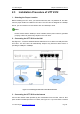
5. Checking the LEDs
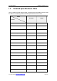
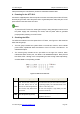
The LEDs are located on the front panel of the UTT 2512, see Figure 2-2. We divide the
LEDs into two groups:
Ɣ The first group includes four system LEDs on the left two columns, which indicate
power status, operational status and failures of the UTT 2512, see Table 2-1 for
detailed description.
Ɣ The second group includes the ten port LEDs on the right five columns, which
indicate the status of each port, see Table 2-2 for detailed description. Each port has
two LEDs, LEDs 1 through 4 are corresponding to LAN1 through LAN4 respectively,
and LED WAN is corresponding to WAN.
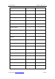
Figure 2-2 LEDs on the UTT 2512
LEDs Status During Startup Status During Operating
SYS
One second after powering up,
the LED flashes fast for one
second, and then extinguishes for
two seconds, lastly flashes twice
per second.
The LED flashes twice per second when the system
is operating properly, and it will flash slower if the
system is under heavy load.
The LED will extinguish or light steady if a fault
occurred in the Device.
PWR
The LED lights during startup.
The LED lights steady when the power is being
supplied to the Device.