
User's Manual

NT210 User’s manual
- 10 -
5 Interface signal
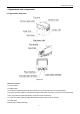
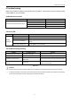
5.1USB interface
Support USB2.0 protocol.
Connector (printer side): Type-C socket
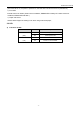
Signal definition and function description are as follows:
Pin No. Signal name Description
1 VBUS +5V
2 DATA-
Printer data transmission negative
phase end.
3 DATA+
Printer data transmission positive
phase end.
4 GND Ground
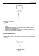
Figure 5.1-1 USB connector diagram
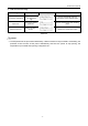
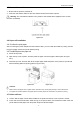
5.2 Power interface
1) Pin definition
The brown line is the fire line and the blue line is the zero line. There is no need to distinguish between
the positive and negative poles.
2) Interface type
Printer side adopts: GB 2PINS, 8-word AC interface
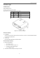
5.3 Cash drawer interface
1) Electrical characteristics
Drive voltage: DC12 V
Drive current: maximum current is 1 A
Cash drawer status detection signal:
“L” = 0~0.5 V“H” =3.3 V
2) Cash drawer interface adopts RJ-12 6P-type connector