
User's Manual

Version 1.0 15JUN2016
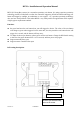
Wiring
DIP Switch Setting:
1
ON
1
No.1,2,4,8,16,32 are used for adjusting door open duration
ON = valid
OFF =invalid
Door open duration=To add all the ON position switch numbers
Example:
If we set #1 and #8 to “ON”, the door open during will be:
1+0+0+8+0+0=9, the decimal number is 9 seconds ( decimal number)
*Setting all DIP Switch to OFF position means door open duration=1sec.
OFF
0
2
ON
2
OFF
0
4
ON
4
OFF
0
8
ON
8
OFF
0
16
ON
16
OFF
0
32
ON
32
OFF
0
RC
ON
RC ON
In certain installation environments, when the device’s maximum
capacitive value is reached, setting RC to the ON position can reset the
baseline of measured capacitive by offsetting a pre-programmed value to
return it to a normalized triggering status.
OFF
RC OFF
FT
ON
FT ON
When FT is set to the ON position. a higher triggering threshold value
will be adopted to prevent false trigger
OFF
FT OFF
Installation:
1) Confirm if the size of installation box fits
for the REX2 as shown in Fig.1
2) Confirm all wirings are in the correct
position, then set the jumpers to the right
position
3) Put the whole module into the installation
box and fixed by screw as Fig.2.
4) There are 2 M-type buckles at the bottom of
the cover as shown in Fig.3. Buckle them
into the slot at the bottom of the module and
push the upper part of the cover up as Fig.4
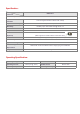
Label
Description
+12V
Power Input (+12VDC)
RTE_COM
Exit Button Output (Dry Contact)
RTE_NO
RTE_NC
MO
Manual Open Input,Active Low
GND
Signal Ground (0 VDC)
Fig.1
Fig.4
Fig.3
Fig.2
M-type Buckles