
User's Manual

Smart Machine Smart Decision
SIM7100A_User Manual_V1.01 2014-12-11
53
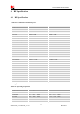
Table 35: Sink Current Electronic characteristic
Symbol Description Min Typ Max Unit
ISINK Input voltage 0.5 VDD VBAT V
I
O
Input current 5 - 40 mA
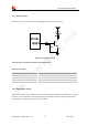
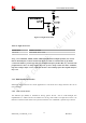
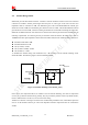
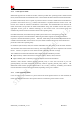
Since the driver is ground-referenced current sink, the operating device it drives must form a current path
between the VDD pin and the ISINK pin. The following figure is for users reference.
MODULE
ISINK
Pin 45 is VBAT tolerant-
suitable for driving white
LEDs
Current Controls
Passive
device
+
-
VBAT
High
current
Figure 32: Current drive
Note: The sinking current can be adjusted to meet design requirement through the AT command “AT+
CLEDITST =<0>, <value>”.The “value” ranges from 0 to 15,on behalf of the current changes from
0mA to 150mA in steps of 10mA.
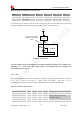
3.14.2 ADC
SIM7100A has a dedicated ADC that is available for digitizing analog signals such as battery voltage and
so on; it is on PIN 47 and PIN 46 , namely ADC1 and ADC2 . This ADC is 15 bit
successive-approximation circuit, and electronic specification is shown in the following table.
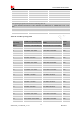
Table 36: Electronic Characteristics
Specification
Min Typ Max Unit Comments/Conditions
Resolution 15 Bits
Analog input bandwidth
–
100 –
kHz
Analog Vdd = ADC reference
2.4MHz sample rate
Gain Error -2.5 +2.5 %
Offset Error -3.5 +3.5 LSB
Input Range GND 2.2V V