
User's Manual

Smart Machine Smart Decision
SIM7100A_User Manual_V1.01 2014-12-11
49
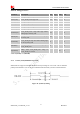
V
IL
Low-level input voltage
-0.3 0 0.63 V
V
OH
High-level output voltage
1.35 - 1.8 V
V
OL
Low-level output voltage
0 0 0.45 V
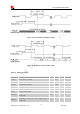
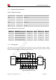
3.11 GPIO Interface
SIM7100A provides a limited number of GPIO pins. All GPIOs can be configured as inputs or outputs.
User can use AT Commands to read or write GPIOs status. Refer to ATC document for details.
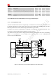
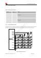
3.11.1 GPIO Pin Description
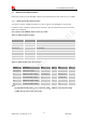
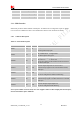
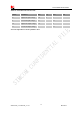
Table 31: GPIO Pin description
Note: If more GPIOs need to be used, users can configure GPIO on other multiple function interfaces,
such as PCM. Please refer to GPIO list.
Pin name Pin No. I/O Function
GPIO1 51 O
Output PIN as LED control for network status. If
unused, please keep open.
GPIO4 54 I
Input PIN as RF operating control.
H: Normal Mode L:Flight Mode
If unused, please keep open .
GPIO40 49 O
Output PIN as operating status indicating of module.
H: Power on L: Power off
It also can output a clock signal for PCM clock source.
If unused, left open.
GPIO41 52 I/O
General input/output PIN. It can be used as
wake/interrupt signal to host from module If unused,
left open.
GPIO42 53 I/O
General Purpose Input/Output Port.
It can be configured as USIM card detecting.
GPIO43 50 I/O
General Purpose Input/Output Port. It can be used as
wake/interrupt signal to module from host. If unused,
left open.
GPIO44 48 I/O
General Purpose Input/Output Port.
It can be configured as SD detecting.