
User's Manual

Smart Machine Smart Decision
SIM7100A_User Manual_V1.01 2014-12-11
48
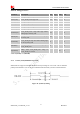
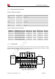
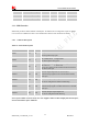
If these pins are configured for GPIOs, the sequence is listed in the following table.
Table 28: Keypad multiplexing function
Pin name Pin number Mode 0(default) Mode 1
KBR4 34 KBR4 GPIO6
KBR3 35 KBR3 GPIO7
KBR2 30 KBR2 GPIO8
KBR1 33 KBR1 GPIO9
KBR0 29 KBR0 GPIO10
KBC4 36 KBC4 GPIO11
KBC3 32 KBC3 GPIO12
KBC2 31 KBC2 GPIO13
KBC1 27 KBC1 GPIO14
KBC0 28 KBC0 GPIO15
Note: Refer to document [23] for detailed information of Keypad Application Note.
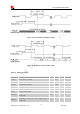
3.10 SPI Interface
SPI interface of SIM7100A is master only. It provides a duplex, synchronous, serial communication link
with peripheral devices. Its operation voltage is 1.8V, with clock rates up to 26 MHz.
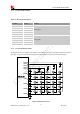
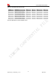
3.10.1 SPI Pin Description
Table 29: SPI Pin description
Table 30: SPI Electronic characteristic
Symbol Parameter
Min Typ Max Unit
V
IH
High-level input voltage
1.26 1.8 2.1 V
Pin name Pin No. Function
SPI_CS 9
SPI chip-select; not mandatory in a point-to-point connection
SPI_MISO 7 SPI master in/slave out data
SPI_CLK 6
SPI clock
SPI_MOSI 8 SPI master out/slave in data