
User's Manual

Smart Machine Smart Decision
SIM7100A_User Manual_V1.01 2014-12-11
46
3.8 I2C Interface
I2C is used to communicate with peripheral equipments and can be operated as either a transmitter or
receiver, depending on the device function. Use AT Commands “AT+CRIIC and AT+CWIIC” to read/write
register values of related peripheral equipments connected with I2C interface. Its operation voltage is
1.8V.
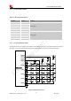
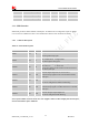
3.8.1 I2C Pin Description
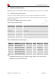
Table 26: I2C Pin description
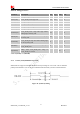
3.8.2 I2C Signal Description
Both SDA and SCL are bidirectional lines, connected to a positive supply via a pull-up resistor
respectively. When the bus is free, both lines are high.
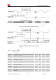
3.8.3 I2C Design Guide
For SIM7100A, the data on the I2C bus can be transferred at rates up to 400kbps. The number of
peripheral devices connected to the bus is solely dependent on the bus capacitance limit of 400pF. Note
that PCB traces length and bending are in users’ control to minimize load capacitance.
Note
:
SDA and SCL have none pulled up resistors in module. So there is need to pull them up in users’
application circuit.
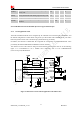
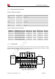
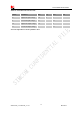
3.9 Keypad Interface
SIM7100A module provides a keypad interface that supports five sense lines, or columns, and five keypad
rows. The interface generates an interrupt when any key is pressed. Its operation voltage is 1.8V.
Pin name Pin No. Function
SDA 56 Serial interface data input and output
SCL 55 Serial interface clock input