
User's Manual

Smart Machine Smart Decision
SIM7100A_User Manual_V1.01 2014-12-11
39
SIM7100A is always a master. SIM7100A also supports 3 kinds of coding formats: 8 bits (-law or A-law)
and 16 bits (linear).
Note: PCM interface is multiplexed from GPIO (default setting). The AT command “AT+CPCM” is
used to switch between PCM and GPIO functions. Please refer to document [21] and document [1] for
details.
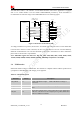
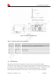
3.6.1 PCM Pin Description
Table 18: PCM Pin description
Pins Pin No. Description
PCM_OUT 73 PCM data output
PCM_IN 74 PCM data input
PCM_SYNC 75 PCM data synchrony
PCM_CLK 76 PCM data clock
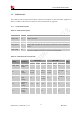
Table 19: PCM Electronic characteristic
Symbol Parameter
Min Typ Max Unit
V
IH
High-level input voltage
1.26 1.8 2.1 V
V
IL
Low-level input voltage
-0.3 0 0.63 V
V
OH
High-level output voltage
1.35 - 1.8 V
V
OL
Low-level output voltage
0 0 0.45 V
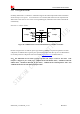
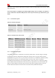
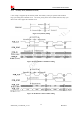
3.6.2 PCM Signal Description
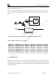
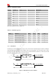
The default PCM interface in SIM7100A is the auxiliary PCM interface. The data changes on the high
level of PCM_CLK and is sampled at the falling edge of PCM_CLK in one period. Primary PCM is
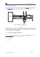
disabled after every power-on or every reset event. So user must use AT command to enable the primary
PCM mode after powering on or resetting the module every time if user wants to use Primary
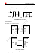
PCM.SIM7100A PCM Interface can be operated in Master or Slave mode if it is configured to primary
PCM. In Master Mode, the Module drives the clock and sync signals that are sent to the external codec.
When it is in Slave Mode, the external codec drives the clock and sync signals which are sent to the
module. Both PCM modes are discussed in this section followed by additional PCM topics.