
User's Manual

Smart Machine Smart Decision
SIM7100A_User Manual_V1.01 2014-12-11
31
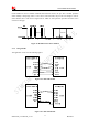
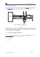
only when AT command “AT+CPOF” and the PWRKEY pin has no effect. User can pull the RESET pin
to ground, then the module will reset.
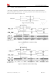
This pin is already pulled up in module, so the external pull-up resistor is not necessary. A 100nF capacitor
close to the RESET pin is strongly recommended. A reference circuit is recommended in the following
figure.
Figure 12: Reset circuit
Note
:
50ms<Treset<200ms. ESD components are suggested to be used on Reset pin.
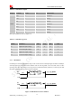
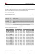
Table 11: RESET Pin Electronic Characteristic
Symbol Description Min Typ Max Unit
V
IH
Input high level
voltage
1.17 1.8 2.1 V
V
IL
Input low level
voltage
-0.3 0 0.63 V
T
reset
Low level pulse width 50 100 200 ms
3.3 UART Interface
SIM7100A provides an UART (universal asynchronous serial transmission) port, consisting of a flexible
7-wire serial interface. The module is as the DCE (Data Communication Equipment) and the client PC is
as the DTE (Data Terminal Equipment). AT commands are entered and serial communication is performed
through UART interface.