
User's Manual

Smart Machine Smart Decision
SIM7100A_User Manual_V1.01 2014-12-11
27
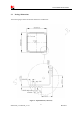
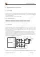
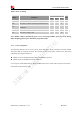
Figure 9: Reference circuit of the DCDC power supply
3.1.3 Volta g e monit o r
To monitor the power supply voltage, user can use the AT command “AT+CBC”, this command has two
parameters: the battery status and the voltage value (mV). It will return the capacity percentage and actual
value of battery (at the VBAT pin). The voltage is continuously measured at intervals, whenever the
measured battery voltage is lower than a specific value set by the AT command “AT+CVALARM”. For
example, if the voltage value is set to be 3.4V, the following URC will be presented: “warning! voltage is
low: 3.3v”.
If the voltage is lower than a specific value which is set by the AT command “AT+CPMVT”, the module
will be powered off automatically and AT commands cannot be executed any more.
Note: Under-voltage warning function and under-voltage power-off function are disabled by default.
For more information about these AT command, please refer to Document [1].
3.2 Power on/Power off/Reset Time Sequence
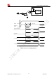
3.2.1 Power on Sequence
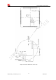
SIM7100A can be powered on by PWRKEY pin, which starts normal operating mode.
PWRKEY pin is pulled up with a 200k ohm resistor to 1.8V in module. User can power on the SIM7100A
by pulling the PWRKEY pin down for a short time. The power-on scenarios are illustrated in the following
figures.