
User's Manual

Smart Machine Smart Decision
SIM7100A_User Manual_V1.01 2014-12-11
20
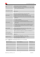
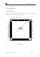
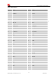
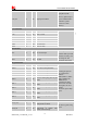
PCM_SYNC 75 DO
PCM data frame sync signal. It
also can be multiplexed as
GPIO2.
PCM_CLK 76 DO
PCM data bit clock. It also can be
multiplexed as GPIO3.
GPIOs
GPIO1 51 DO
Output as LED control for
network status.
If unused, keep open.
GPIO4 54 DI Input as RF operating control.
GPIO40 49 DO
Output as operating status
indicating of module.
It also can output a clock signal
for PCM clock source.
GPIO41 52 DO
General input/output. It can be
used as wake/interrupt signal to
host from module
GPIO43 50 DI
General input/output. It can be
used as wake/interrupt signal to
module from host.
GPIO44 48 I/O
General input/output.
It can be configured as SD
detecting.
GPIO42 53 I/O
General input/output.
It can be configured as USIM
card detecting.
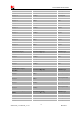
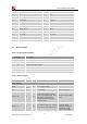
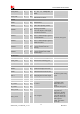
RF interface
MAIN _ANT 82 MAIN antenna soldering pad
GNSS_ANT 79 AI GNSS antenna soldering pad
AUX_ANT 59 AI Diversity antenna soldering pad
Other interface
RESET 4 DI System reset input, active low.
ISINK 45 DI
Current source of
ground-referenced current sink
If unused, please keep
open.
ADC1 47 AI Analog Digital Converter Input
ADC2 46 AI Analog Digital Converter Input
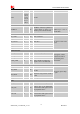
RF_CFG1 83 I/O
RF control
They are used to
control RF when
SDIO function is
used.
If unused, keep open.
RF_CFG2 84 I/O
RF_CFG3 86 I/O
BOO_CFG0 85 DI
Boot configure
Recommend placing 2
test points for
debugging. Module
will be forced to go
into USB download
mode by connect 85
and 87 pins to
VDD_1V8 during
power up.
BOO_CFG1 87 DI