
User's Manual

Smart Machine Smart Decision
SIM7100A_User Manual_V1.01 2014-12-11
11
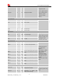
LTE-FDD B13
LTE-FDD B17
LTE-FDD B20
LTE-TDD
LTE TDD B38
LTE TDD B39
LTE TDD B40
LTE TDD B41
(100M BW)
With a tiny configuration of 30*30*2.9 mm and integrated functions, SIM7100A can meet almost any
space requirement in users’ application, such as Smart phone, PDA phone, industrial handhelds,
machine-to-machine, vehicle applications, etc.
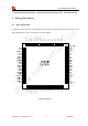
There are 87 pins on SIM7100A, which provide most application interfaces for customers’ board.
1.2 Hardware Interface Overview
Sub-interfaces are described in detail in the next chapter, which includes:
● Power Supply
● USB Interface
● UART Interface
● MMC/SD and SDIO Interfaces
● USIM Interface
● GPIO
● ADC
● LDO Power Output
● Current Sink Source
● PCM Interface
● Keypad Interface
● SPI Interface
● I2C Interface
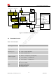
1.3 Hardware Diagram
The global architecture of the SIM7100A Embedded module is described in the figure below.