SIM7100A_User Manual_V1.
Smart Machine Smart Decision Document Title SIM7100A_User Manual_V1.01 Version 1.01 Date 2014-12-11 Status Draft Document Control ID SIM7100A_User Manual_V1.01 General Notes SIMCom offers this information as a service to its customers, to support application and engineering efforts that use the products designed by SIMCom. The information provided is based upon requirements specifically provided to SIMCom by the customers.
Smart Machine Smart Decision Contents SIM7100A_User Manual_V1.01................................................................................................................. 1 Contents........................................................................................................................................................ 3 Table Index ...................................................................................................................................................
Smart Machine Smart Decision 3.7 MMC/SD and SDIO Interface ....................................................................................................... 44 3.7.1 MMC/SD Interface Pin Description ....................................................................................... 44 3.7.2 SDIO Interface Pin Description .............................................................................................. 45 3.7.3 SD Design guide ..........................................................
Smart Machine Smart Decision A. Reference Design ................................................................................................................................ 70 B. SIM7100A GPIOs List ........................................................................................................................ 71 C. Digital I/O Characteristics ................................................................................................................... 71 D. Related Documents ............
Smart Machine Smart Decision Table Index Table 1: SIM7100A series frequency bands .................................................................................................................... 10 Table 2: General Feature ................................................................................................................................................. 12 Table 3: Coding schemes and maximum net data rates over air interface .................................................................
Smart Machine Smart Decision Table 43: Absolute maximum ratings.............................................................................................................................. 63 Table 44: Recommended operating ratings ..................................................................................................................... 63 Table 45: Operating temperature ..............................................................................................................................
Smart Machine Smart Decision Figure Index Figure 1: SIM7100A functional architecture................................................................................................................... 12 Figure 2: Pin view ........................................................................................................................................................... 15 Figure 3: Top dimensions (Unit: mm) ..............................................................................................
Smart Machine Smart Decision Revision History Data Version Description of change Author 2014-12-11 1.01 Original Yang Hongliang Li Ya SIM7100A_User Manual_V1.
Smart Machine Smart Decision 1 Introduction This document describes electronic specifications, RF specifications, function interface, mechanical characteristic and testing conclusions of the SIMCom SIM7100A module. With the help of this document and other SIM7100A software application notes, user guides, users can quickly understand and use SIM7100A module to design and develop applications quickly. 1.
Smart Machine Smart Decision LTE-FDD B13 LTE-FDD B17 LTE-FDD B20 LTE TDD B38 LTE TDD B39 LTE-TDD LTE TDD B40 LTE TDD B41 (100M BW) With a tiny configuration of 30*30*2.9 mm and integrated functions, SIM7100A can meet almost any space requirement in users’ application, such as Smart phone, PDA phone, industrial handhelds, machine-to-machine, vehicle applications, etc. There are 87 pins on SIM7100A, which provide most application interfaces for customers’ board. 1.
Smart Machine Smart Decision GNSS Antenna Main Antenna DDR DIV Antenna NAND Flash GNSS RF WCDMA/LTE RF FEM WCDMA /LTE RF FEM SMT Interface Qualcomm Chip Processor RF Transceiver RF GSM WCDMA/LTEPA Vbat* RF WCDMA/LTEFDD PA Power Management USIM UART MMC/SD/SDIO I2C PCM USB Interrupt GPIOs ADC Status LED LDO SPI Keypad(Multiplex with GPIOs) Sink Current Source Power On Reset Vbat* XO 19.2MHz Figure 1: SIM7100A functional architecture 1.
Smart Machine Smart Decision MT, MO, CB, Text and PDU mode ● SMS storage: USIM card or ME(default) ● Support transmission of SMS alternatively over CSD or GPRS. User can choose preferred mode. ● SMS USIM interface USIM application toolkit Phonebook management Audio features UART interface Support identity card: 1.8V, 3V. Support SAT class 3, GSM 11.14 Release 98 Support USAT Support phonebook types: SM, FD, LD, RC, ON, MC. Support digital audio interface: PCM interface.
Smart Machine Smart Decision Category 8 7.2Mbps 16QAM,QPSK Category 9 10.2Mbps 16QAM,QPSK Category 10 14.4Mbps 16QAM,QPSK Category 11 0.9Mbps QPSK Category 12 1.8Mbps QPSK Category 13 17.6Mbps 64QAM Category 14 21.1Mbps 64QAM Category 15 23.4Mbps 16QAM Category 16 28Mbps 16QAM Category 17 23.4Mbps 64QAM Category 18 28Mbps 64QAM Category 19 35.5Mbps 64QAM Category 20 42Mbps 64QAM Category 21 23.4Mbps 16QAM Category 22 28Mbps 16QAM Category 23 35.
Smart Machine Smart Decision Category 4 50Mbps QPSK/16QAM 2 Package Information 2.
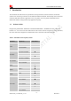
Smart Machine Smart Decision Table 4: Pin definition Pin No. Define Pin No.
Smart Machine Smart Decision 67 CTS 68 RXD 69 RI 70 DCD 71 TXD 72 DTR 73 PCM_OUT 74 PCM_IN 75 PCM_SYNC 76 PCM_CLK 77 GND 78 GND 79 GNSS_ANT 80 GND 81 GND 82 MAIN_ANT 83 RF_CFG1 84 RF_CFG2 85 BOOT_CFG0 86 RF_CFG3 87 BOOT_CFG1 2.
Smart Machine Smart Decision circuit. GND 1,2,5,10 ,14,37,4 0,41,43, 57,58,6 0,61,64, 65,77,7 8,80,81 Ground Power on/off 3 DI PWRKEY should be pulled low at least 180ms to power on or 500ms to power off the module.
Smart Machine Smart Decision USB_ID 16 DI High-speed USB ID RTS 66 DO Request to send CTS 67 DI Clear to Send RXD 68 DI Receive Data RI 69 DO Ring Indicator DCD 70 DO Carrier detects TXD DTR 71 72 DO DI Transmit Data DTE get ready SCL 55 DO I2C clock output SDA 56 I/O I2C data KBR0 29 DO Bit 0 drive to the pad matrix KBR1 33 DO Bit 1 drive to the pad matrix KBR2 30 DO Bit 2 drive to the pad matrix KBR3 35 DO Bit 3 drive to the pad matrix KBR4 34 DO Bit
Smart Machine Smart Decision PCM data frame sync signal. It also can be multiplexed as GPIO2. PCM data bit clock. It also can be multiplexed as GPIO3. PCM_SYNC 75 DO PCM_CLK 76 DO GPIO1 51 DO Output as LED control for network status. GPIO4 54 DI Input as RF operating control. GPIOs GPIO40 49 DO GPIO41 52 DO GPIO43 50 DI GPIO44 48 I/O GPIO42 53 I/O Output as operating status indicating of module. It also can output a clock signal for PCM clock source. General input/output.
Smart Machine Smart Decision 2.3 Package Dimensions The following figure shows mechanical dimensions of SIM7100A. Figure 3: Top dimensions (Unit: mm) SIM7100A_User Manual_V1.
Smart Machine Smart Decision Figure 4: Side dimensions (Unit: mm) SIM7100A_User Manual_V1.
Smart Machine Smart Decision Figure 5: Bottom dimensions (Unit: mm) SIM7100A_User Manual_V1.
Smart Machine Smart Decision 2.4 Footprint Recommendation Figure 6: Footprint recommendation (Unit: mm) SIM7100A_User Manual_V1.
Smart Machine Smart Decision 3 Application Interface Specification 3.1 Power Supply The power supply pins of SIM7100A include four VBAT pins (pin 62&63, pin 38&39). VBAT directly supplies the power to RF and baseband circuit. VBAT directly supplies the power to RF PA and baseband system. Power Supply Pin 4 VBAT pins are dedicated to connect the supply voltage. Table 7: VBAT Pin description Pin type Pin name Min Typ Max Unit POWER VBAT 3.15 3.8 4.2 V 3.1.
Smart Machine Smart Decision Cf must be mounted. In addition, in order to get a stable power source, it is suggested to use a zener diode of which reverse zener voltage is 5.1V and dissipation power is more than 500mW. Table 8: Recommended zener diode models No. Manufacturer Part Number Power Package 1 On semi MMSZ5231BT1G 500mW SOD123 2 Prisemi PZ3D4V2H 500mW SOD323 3 Vishay MMSZ4689-V 500mW SOD123 4 Crownpo CDZ55C5V1SM 500mW 0805 3.1.
Smart Machine Smart Decision Figure 9: Reference circuit of the DCDC power supply 3.1.3 Voltage monitor To monitor the power supply voltage, user can use the AT command “AT+CBC”, this command has two parameters: the battery status and the voltage value (mV). It will return the capacity percentage and actual value of battery (at the VBAT pin). The voltage is continuously measured at intervals, whenever the measured battery voltage is lower than a specific value set by the AT command “AT+CVALARM”.
Smart Machine Smart Decision 1.8V 200K Power On / off logic PWRKEY 4.7K Turn on / off impulse VBAT PWRKEY (Input) 47K MODULE Ton VIH >1.6V VIL<0.3V Tpd+ NETLIGHT/GPIO1 (Output) Tpw+ VDD_EXT (Output) Tuart UART Port Active Undefined Tusb USB Port Undefined Active Figure 10: Power on Timing Sequence SIM7100A_User Manual_V1.
Smart Machine Smart Decision Table 9: Power on timing Symbol Time value Parameter Unit Min. Typ. Max. 180 500 - ms - 5 s - 0.5 Ton The time to pull PWRKEY down to power on TpD+ The time to indicate connecting with the network - Tpw+ The time to indicate the module is powered on completely - Tuart The time to enable UART - - 8 s Tusb The time to enable USB - - 10 s s Note: Module could be automatically power on by connecting PWRKEY pin to Low level directly.
Smart Machine Smart Decision Trestart PWRKEY ( Input ) Toff Ton VIL <0.3V VIL <0.3V NETLIGHT/GPIO1 ( Output ) TpdVDD_EXT ( Output ) Tpw- Tuart Active UART Port Undefined Tusb Active USB Port Undefined Figure 11: Power off timing sequence Table 10: Power off timing Symbol Time value Parameter Min. Typ. Max. Unit 0.
Smart Machine Smart Decision only when AT command “AT+CPOF” and the PWRKEY pin has no effect. User can pull the RESET pin to ground, then the module will reset. This pin is already pulled up in module, so the external pull-up resistor is not necessary. A 100nF capacitor close to the RESET pin is strongly recommended. A reference circuit is recommended in the following figure. Figure 12: Reset circuit Note:50ms
Smart Machine Smart Decision Table 12: UART Pin description Pin type UART1 Pin name Pin No. I/O Default Status RXD 68 I Pull-Down TXD 71 O Pull-Up RTS 66 O Pull-Up CTS 67 I Pull-Down DTR 72 I Pull-Up DCD 70 O Pull-Up RI 69 O Pull-Up More pin information refers to chapter 2.2. Table 13: UART Pin Logic level Symbol Parameter Min Typ Max Unit VIH High-level input voltage 1.26 1.8 2.1 V VIL Low-level input voltage -0.3 0 0.
Smart Machine Smart Decision If Full Modem is used to establish communication between devices, the pin “RI” is another operation status. Initially it keeps high, when a voice call or CSD call comes, the pin “RI” will change to low for about 5900ms, then it will return to high level for 100ms. It will repeat this procedure until this call is answered or hung up. Figure 14: RI behaviour in FULL Modem 3.3.2 Design Guide The application circuit is in the following figures.
Smart Machine Smart Decision The SIM7100A UART is 1.8V interface. A level shifter should be used if user’s application is equipped with a 3.3V UART interface. The level shifter TXB0108RGYR provided by Texas Instruments is recommended. The reference design of the TXB0108RGYR is in the following figures. VDD_1V8 or External 1V8 3.3V TXB0108RGYR 100nF MODULE TXD RXD RTS CTS DTR DCD RI 47K UART port 100nF VCCA VCCB OE GND A1 A2 A3 A4 A5 A6 A7 B1 B2 B3 B4 B5 B6 B7 A8 B8 47K TXD_3.3V RXD_3.3V RTS_3.
Smart Machine Smart Decision 3.4.1 USB Application Guide Normally, SIM7100A is a USB device. SIM7100A supports the USB suspend and resume mechanism which can help to save power. If no transaction is on USB bus, SIM7100A will enter suspend mode. When some events such as voice call or receiving SMS happen, SIM7100A will resume normal mode automatically. SIM7100A is a USB host controller. Figure 18: USB Reference Circuit with SIM7100A as USB Host Controller.
Smart Machine Smart Decision 3.5 USIM Interface The USIM provides the required subscription verification information to allow the mobile equipment to attach to a GSM or UMTS network. Both 1.8V and 3.0V SIM Cards are supported. 3.5.1 USIM Pin description Table 15: USIM Pin description Pin name Pin Description USIM_CLK 19 USIM Card Clock USIM_RST 18 USIM_DATA 17 USIM_VDD 20 USIM Card Reset USIM Card data I/O, which has been pulled up with a 22kR resistor to USIM_VDD in module.
Smart Machine Smart Decision 3.5.2 USIM Application Guide It is recommended to use an ESD protection component such as ST (www.st.com ) ESDA6V1W5 or ON SEMI (www.onsemi.com ) SMF05C. Note that the SIM peripheral circuit should be close to the SIM card socket. The reference circuit of the 6-pin SIM card holder is illustrated in the following figure. Figure 19: USIM interface reference circuit Note: USIM_DATA has been pulled up with a 15kohm resistor to USIM_VDD in module.
Smart Machine Smart Decision Figure 20: Amphenol SIM card socket Table 17: Amphenol USIM socket pin description Pin Signal C1 USIM_VDD C2 USIM_RST SIM Card Reset. C3 C5 C6 C7 USIM_CLK GND VPP USIM_DATA SIM Card Clock. Connect to GND. 3.6 Description SIM Card Power supply, it can identify automatically the SIM Card power mode,one is 3.0V±10%, another is 1.8V±10%. SIM Card data I/O. PCM Interface SIM7100A provides hardware PCM interface for external codec.
Smart Machine Smart Decision SIM7100A is always a master. SIM7100A also supports 3 kinds of coding formats: 8 bits (-law or A-law) and 16 bits (linear). Note: PCM interface is multiplexed from GPIO (default setting). The AT command “AT+CPCM” is used to switch between PCM and GPIO functions. Please refer to document [21] and document [1] for details. 3.6.1 PCM Pin Description Table 18: PCM Pin description Pins Pin No.
Smart Machine Smart Decision 3.6.3 Auxiliary PCM (128 KHz PCM clock) -law coding is supported by the auxiliary PCM. The auxiliary codec port operates with standard long-sync timing and a 128 KHz clock. The AUX_PCM_SYNC runs at 8 KHz with 50% duty cycle. Most -law codec support the 128 KHz clock. Figure 21: Synchrony timing Figure 22: EXT CODEC to MODULE timing Figure 23: MODULE to EXT CODEC timing SIM7100A_User Manual_V1.
Smart Machine Smart Decision Table 20: Timing parameters Parameter Description Min Typ Max Unit T(auxsync) AUX_PCM_SYNC cycle time – 125 - μs T(auxsynch) AUX_PCM_SYNC high time 62.4 62.5 - μs T(auxsyncl) AUX_PCM_SYNC low time 62.4 62.5 - μs T(auxclk)* AUX_PCM_CLK cycle time - 7.8 – μs T(auxclkh) AUX_PCM_CLK high time 3.8 3.9 – μs T(auxclkl) AUX_PCM_CLK low time 3.8 3.9 – μs T(suauxsync) AUX_PCM_SYNC setup time high before falling edge of PCM_CLK 1.
Smart Machine Smart Decision Figure 25: EXT CODEC to MODULE timing Figure 26: MODULE to EXT CODEC timing Table 21: Timing parameters Parameter Description Min Typ Max Unit T(sync) PCM_SYNC cycle time – 125 – μs T(synch) PCM_SYNC high time 400 500 – ns T(syncl) PCM_SYNC low time – 124.
Smart Machine Smart Decision T(sudin) PCM_IN setup time before falling edge of PCM_CLK 50 – – ns T(hdin) PCM_IN hold time after falling edge of PCM_CLK 10 – – ns T(pdout) Delay from PCM_CLK rising to PCM_OUT valid – – 350 ns T(zdout) Delay from PCM_CLK falling to PCM_OUT HIGH-Z – 160 – ns Note: SIM7100A can transmit PCM data by USB except for PCM interface. 3.6.
Smart Machine Smart Decision 3.7 MMC/SD and SDIO Interface SIM7100A provides one 4-bit SD/MMC interface and one SDIO interface with clock rate up to 52 MHz. 3.7.1 MMC/SD Interface Pin Description The operation voltage of MMC/SD interface is 2.85V. It supports 1-bit SD/MMC or 4-bit SD data transmission mode. Though the same hardware controller is used, the initialization procession for SD or MMC cards is different.
Smart Machine Smart Decision 3.7.2 SDIO Interface Pin Description Table 24: SDIO Pin description Pin name Pin No. Function KBR2 30 SD2_DATA0 KBC1 27 SD2_DATA1 KBC0 28 SD2_DATA2 KBC2 31 SD2_DATA3 KBR0 29 SD2_CMD KBC3 32 SD2_CLK Table 25: SDIO Electronic characteristic Symbol Parameter VIH High-level input voltage 1.26 1.8 2.1 V VIL Low-level input voltage -0.3 0 0.63 V VOH High-level output voltage 1.35 - 1.8 V VOL Low-level output voltage 0 0 0.45 V 3.7.
Smart Machine Smart Decision 3.8 I2C Interface I2C is used to communicate with peripheral equipments and can be operated as either a transmitter or receiver, depending on the device function. Use AT Commands “AT+CRIIC and AT+CWIIC” to read/write register values of related peripheral equipments connected with I2C interface. Its operation voltage is 1.8V. 3.8.1 I2C Pin Description Table 26: I2C Pin description Pin name SDA Pin No.
Smart Machine Smart Decision 3.9.1 Keypad Pin Description Table 27: Keypad Pin description Pin name Pin No. Function KBC0 KBC1 KBC2 28 27 31 Sensing keys KBC3 32 KBC4 KBR0 KBR1 KBR2 KBR3 KBR4 36 30 29 30 35 34 3.9.2 Driving pads Keypad Application Guide All keypad pins can be configured for GPIOs. These GPIOs also support interruption operation if used as input pins. A typical circuit about the keypad (5*5 keypad matrix) is shown in the following figure.
Smart Machine Smart Decision If these pins are configured for GPIOs, the sequence is listed in the following table.
Smart Machine Smart Decision VIL Low-level input voltage -0.3 0 0.63 V VOH High-level output voltage 1.35 - 1.8 V VOL Low-level output voltage 0 0 0.45 V 3.11 GPIO Interface SIM7100A provides a limited number of GPIO pins. All GPIOs can be configured as inputs or outputs. User can use AT Commands to read or write GPIOs status. Refer to ATC document for details. 3.11.1 GPIO Pin Description Table 31: GPIO Pin description Pin name Pin No.
Smart Machine Smart Decision Table 32: GPIO Electronic characteristic Symbol Parameter Min Typ Max Unit VIH High-level input voltage 1.26 1.8 2.1 V VIL Low-level input voltage -0.3 0 0.63 V VOH High-level output voltage 1.35 - 1.8 V VOL Low-level output voltage 0 0 0.45 V Note: The output driver current of GPIOs is 2mA. SIM7100A_User Manual_V1.
Smart Machine Smart Decision 3.12 Network status GPIO1 is used to control Network Status LED; application circuit is shown below. Figure 30: Application circuit Note: The value of resistor Rx depends on LED characteristic. Table 33: LED status LED Status Always On 200ms ON, 200ms OFF 800ms ON, 800ms OFF Module Status Searching Network/Call Connect Data Transmit Registered network Off Power off / Sleep 3.13 Flight mode control GPIO4 controls SIM7100A module to enter or exit the Flight mode.
Smart Machine Smart Decision Figure 31: Flight mode switch Table 34: Flight mode status GPIO4 Status Low Level High Level Module operation Flight Mode: RF is closed. Normal Mode: RF is working. Note:1. For SIM7100A, GPIO0, GPIO2, GPIO3 and GPIO5 have multiplex function, user can use them as PCM interface to connect extend codec. Refer to section 3.11 and document [1] for details. 2.
Smart Machine Smart Decision Table 35: Sink Current Electronic characteristic Symbol Description Min Typ Max Unit ISINK Input voltage 0.5 VDD VBAT V IO Input current 5 - 40 mA Since the driver is ground-referenced current sink, the operating device it drives must form a current path between the VDD pin and the ISINK pin. The following figure is for users reference.
Smart Machine Smart Decision Input serial resistance Power supply current Normal operation Power supply current Off 2 kΩ 1.5 mA 50 200 Sample and hold switch resistance nA User can introduce a signal in the ADC pin directly and use the AT command “AT+CADC” to get the raw data which is between 0 and 32768. The data can be transformed to any type such as voltage, temperature etc. Please refer to document [1]. Note: The input signal voltage value in ADC must not be higher than 2.2V. 3.14.
Smart Machine Smart Decision 4 RF Specification 4.
Smart Machine Smart Decision WCDMA1900 1930~1990 MHz 1850~1910 MHz WCDMA 850 869 ~894 MHz 824 ~849 MHz WCDMA 900 925 ~960 MHz 880 ~915 MHz TDSCDMA 1900 1880~1920 MHz 1880~1920 MHz TDSCDMA 2000 2010~2025 MHz 2010~2025 MHz LTE Operating frequencies are shown in following table 34. Note: Operating frequencies of LTE TDD B41 for SIM7100AC is 100MHz BW, 2555~2655 MHz GPS L1 BAND 1574.4 ~1576.
Smart Machine Smart Decision 26 814 MHz~849 MHz 859 MHz~894 MHz FDD 27 807 MHz~824 MHz 852 MHz~869 MHz FDD 28 703 MHz~748 MHz 758 MHz~803 MHz FDD 31 452.5 MHz~457.5 MHz 462.5 MHz~467.
Smart Machine Smart Decision 4.2 Antenna Design Guide SIM7100A provides RF antenna interface. Customer’s antenna should be located in the host board and connected to module’s antenna pad through micro-strip line or other types of RF trace and the trace impedance must be controlled in 50Ω. The maximum gain of the LTE B2/WCDMA B2 antenna gain should not exceed 3.4dBi, LTE B4 antenna gain should not exceed 1.9 dBi, LTE B5/WCDMA B5 antenna gain should not exceed 2.
Smart Machine Smart Decision Figure 34: Antenna matching circuit (AUX_ANT) In above figure, R1, C1, C2 and R2 are used for diversity antenna matching. By default, the R1, R2 are 0 Ohm resistors, and the C1, C2 are reserved for tuning. 4.3 GNSS (GPS and GLONASS) SIM7100A merges GNSS (GPS/GLONASS) satellite and network information to provide a high-availability solution that offers industry-leading accuracy and performance.
Smart Machine Smart Decision 4.3.2 GNSS Operate Mode SIM7100A supports both A-GPS and S-GPS, and then provides three operating modes: mobile-assisted mode, mobile-based mode and standalone mode. A-GPS includes mobile-assisted and mobile-based mode. In mobile-assisted mode, when a request for position location is issued, available network information is provided to the location server (e.g. Cell-ID) and assistance is requested from the location server.
Smart Machine Smart Decision Figure 35: Active antenna circuit Figure 36: Passive antenna circuit (Default) In above figures, the components C1 and L1, L2 are used for antenna matching, the values of the components can only be obtained after the antenna tuning usually, and they are provided by antenna vendor.C2 in Figure 35 is used for DC isolation.
Smart Machine Smart Decision Note: GNSS is closed by default, it could be started by AT+CGPS. The AT command has two parameters, the first is on/off, and the second is GNSS mode. Default mode is standalone mode. AGPS mode needs more support from the mobile telecommunication network. Refer to AGPS application document for details. SIM7100A_User Manual_V1.
Smart Machine Smart Decision 5 Reliability and Operating Characteristics 5.1 Electronic Characteristics Absolute maximum rating for digital and analog pins of SIM7100A are listed in the following table: Table 43: Absolute maximum ratings Parameter Voltage at digital pins (1.8v digital I/O) Voltage at VBAT Voltage at VRTC Voltage at USB_VBUS Min -0.3 -0.5 2 -0.5 Max 2.1 6.0 3.25 6.0 Unit V V V V Typ 1.8 3.8 5 Max 1.95 4.2 3.2 5.
Smart Machine Smart Decision 5.2 Operating Mode 5.2.1 Operating Mode The table below summarizes the various operating modes of SIM7100Ax. Table 46: Operating mode Mode Status Normal operati on Sleep WCDMA /LTE Module will automatically go into sleep mode if the conditions of sleep mode are enabling and there is no on air and no hardware interrupt (such as USB wake-up operation or data on serial port). In this case, the current consumption of module will be reduced to the minimal level.
Smart Machine Smart Decision 5.2.3 Sleep mode If peripheral equipments stops working, and there is no on air or hardware interrupts (such as GPIO interrupts or data on UART), SIM7100A will enter sleep mode automatically. In this mode, SIM7100A can still receive paging,voice call or SMS from network. If USB interface of SIM7100A is connected to host CPU, but host CPU does not support USB suspending, then SIM7100A will not enter sleep mode. After USB is disconnected, SIM7100A will enter sleep mode.
Smart Machine Smart Decision UMTS Sleep/Idle Mode (with USB suspended) Sleep mode @DRX=9 1.3 mA Sleep mode @DRX=8 1.6 mA WCDMA supply current Sleep mode @DRX=6 3.
Smart Machine Smart Decision 6 Guide for Production 6.1 Top and Bottom View of SIM7100A Figure 37: Top and bottom view of SIM7100A These test points are only used for module manufacturing and testing. They are not for customer’s application. 6.2 Typical Solder Reflow Profile For customer convenience, SIMCom provides a typical example for a commonly used soldering profile.
Smart Machine Smart Decision Figure 38: The ramp-soak-spike reflow profile of SIM7100A For details about secondary SMT, please refer to document [26]. 6.3 Moisture Sensitivity Level (MSL) SIM7100A is qualified to Moisture Sensitivity Level (MSL) 5 in accordance with JEDEC J-STD-033. After the prescribed time limit exceeded, users should bake modules for 192 hours in drying equipment (<5% RH) at 40° C +5° C/-0° C, or 72 hours at 85° C +5° C/-5° C.
Smart Machine Smart Decision 6.4 Stencil Foil Design Recommendation The recommended thickness of stencil foil is more than 0.15mm. SIM7100A_User Manual_V1.
Smart Machine Smart Decision Appendix A. Reference Design Main Antenna GNSS Antenna R102 0R 82 NC C106 C107 NC 57 58 60 Power supply 62 VBAT C101 100uF C102 100nF C103 22pF MAIN_ANT GNSS_ANT GND GND GND VBAT 63 61 GND 64 GND 79 L101 NC GND 77 GND 78 GND 80 AUX_ANT 59 GND 41 VBAT C108 33pF L102 NC 0R R101 C104 Div Antenna C105 NC NC R105 3 POWERKEY >50ms R103 4.
Smart Machine Smart Decision B.
Smart Machine Smart Decision voltage VOL IOH IOL Low-level output voltage High-level output current Low-level output current 0 0 0.45 V - 1 - mA - -1 - mA IIH Input high leakage current - - 1 uA IIL Input low leakage current -1 - - uA CIN Input capacitance - - 7 pF Note: These parameters are for digital interface pins, such as keypad, GPIO, I2C, UART, SPI. Digital I/O specifications under both conditions are presented in the above tables. D.
Smart Machine Smart Decision Electromagnetic Compatibility (EMC) for mobile terminals and ancillary equipment. [11] 3GPP TS 34.124 [12] 3GPP TS 34.121 [13] 3GPP TS 34.123-1 [14] 3GPP TS 34.123-3 [15] EN 301 908-02 V2.2.1 [16] EN 301 489-24 V1.2.1 [17] IEC/EN60950-1(2001) Safety of information technology equipment (2000) [18] 3GPP TS 51.010-1 Digital cellular telecommunications system (Release 5); Mobile Station (MS) conformance specification [19] GCF-CC V3.23.
Smart Machine Smart Decision E.
Smart Machine Smart Decision Rx SIM SMS SPI TDMA TE TX UART VSWR Vmax Vnorm Vmin VIHmax VIHmin VILmax VILmin VImax VImin VOHmax VOHmin VOLmax VOLmin SM NC EDGE HSDPA HSUPA ZIF WCDMA VCTCXO USIM UMTS UART Receive Direction Subscriber Identification Module Short Message Service serial peripheral interface Time Division Multiple Access Terminal Equipment, also referred to as DTE Transmit Direction Universal Asynchronous Receiver & Transmitter Voltage Standing Wave Ratio Maximum Voltage Value Normal Voltage V
Smart Machine Smart Decision F. Safety Caution Table 54: Safety caution Marks Requirements When in a hospital or other health care facility, observe the restrictions about the use of mobiles. Switch the cellular terminal or mobile off, medical equipment may be sensitive to not operate normally for RF energy interference. Switch off the cellular terminal or mobile before boarding an aircraft. Make sure it is switched off.
Smart Machine Smart Decision Contact us: Shanghai SIMCom Wireless Solutions Ltd. Add: SIM Technology Building, No.633, Jinzhong Road, Changning District, Shanghai P.R. China 200335 Tel: +86 21 3235 3300 Fax: +86 21 3235 3301 URL: www.sim.com/wm SIM7100A_User Manual_V1.