Development Kit Manual SIM7100A_EVB_User Guide_V1.
Document Title: SIM7100A EVB User Guide Version: 1.01 Date: 2014-08-20 Status: Release Document Control ID: SIM7100A_EVB_User Guide_V1.01 General Notes SIMCom offers this information as a service to its customers, to support application and engineering efforts that use the products designed by SIMCom. The information provided is based upon requirements specifically provided to SIMCom by the customers.
Smart Machine Smart Decision Contents Contents...............................................................................................................................................2 Figure Index........................................................................................................................................ 2 Table Index..........................................................................................................................................2 Version History...
Smart Machine Smart Decision Table Index TABLE 1:SIM7100A EVB KEY FEATURES.......................................................................................2 TABLE 2: SIM CARD SOCKET..........................................................................................................2 TABLE 3: SERIAL INTERFACE......................................................................................................... 2 TABLE 4: NETWORK STATUS LED........................................................
Smart Machine Smart Decision 1 Overview This document gives the usage of SIM7100A EVB, user can get useful information about the SIM7100A EVB quickly through this document. All the functions of the SIM7100A can be used by this board. NOTE: This document is subject to change without notice at any time. Table 1:SIM7100A EVB Key features Feature Implementation Power supply DC 6.0V~9.0V functions SIM7100A EVB user Guide DC adapter power supply Handset interface UART interface USB2.
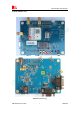
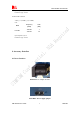
Smart Machine Smart Decision 2 SIM7100A EVB FIGURE 1: EVB view SIM7100A EVB user Guide 5 20.08.
Smart Machine Smart Decision A: B: C: D: E: F: G: H: I: J: L: M: N: O: P: SIM7100A module Reset keypad Power on/off keypad IO interface(including GPIO,ADC,SPI,etc) LED indicator(including network status,operating status) Power supply selection jumper UART enable/disable switch RF enable/disable (flight mode) switch USB connector SIM card socket Main antenna SMA Handset connector UART connector Adapter connector SIM7100A JTAG test point All hardware Sub-interfaces included in SIM7100A EVB are described in
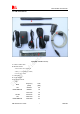
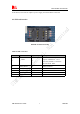
Smart Machine Smart Decision 3 EVB accessories FIGURE 2: EVB accessory A: USB to UART cable B: RFGPS antenna Antenna Model: WT-C&G-28-90 VSWR ≤1.5 (1500MHz≤f≤1700Mz) Connector Type: SMA C: USB cable D: 6V DC adapter E: RF 3G/4G antenna Gain: Frequency Gain (MHz) (dBi) LTE 824-849 2.8 B5/WCDMA B5 869-894 1.8 Band 1710-1755 1.9 LTE B4 2110-2155 2.6 LTE 1850-1910 3.4 B2/WCDMA B2 1930-1990 3.2 SIM7100A EVB user Guide 7 20.08.
Smart Machine Smart Decision Input Impedance (Ω): 50 Polarization Type: Vertical F: RF 4G B17 antenna VSWR ≤1.5 (650MHz) ≤2 (2155MHz) Gain: Band Frequency Gain LTE B17 (MHz) (dBi) 704-706 1 734-746 1.3 Input Impedance (Ω): 50 Polarization Type: Vertical 4 Accessory Interface 4.1 Power Interface FIGURE 3: DC adapter interface FIGURE 4: Power supply jumper SIM7100A EVB user Guide 8 20.08.
Smart Machine Smart Decision In this board, if user uses DC adapter as power supply, the J203 should be connected. 4.2 SIM card interface FIGURE 5: SIM card socket Table 2: SIM card socket Pin 1 Signal V_USIM Input/Output Description O USIM Card Power output automatic output on USIM mode,one is 3.0V±10%, another is 1.8V±10%. Current is about 10mA.
Smart Machine Smart Decision 4.3 Antenna Interface FIGURE 6: Main Antenna connector 4.4 RS232 Interface FIGURE 7: UART interface J401 is 9 pins standard RS232 UART interface. It can be connected to a PC directly.
Smart Machine Smart Decision 4.5 Operating Status LED FIGURE 8: Status LED Table 4: Network status LED D301 Status Module Status Off On Module is not running Module is running, or voice call is connected 800ms On/ Off Module find the network and registered 200ms On/ Off Data communication LED I/O Description D202 O ADAPTER power indicator 4.6 USB interface FIGURE 9: USB Interface It is a normal 4Pin USB connector.
Smart Machine Smart Decision 4.7 Switch interface FIGURE 10: Switch Interface Table 6: Switch interface Switch Signal I/O Description 1 RS232 chip SHUTDOWN I UART switch 2 GPIO4 I RF switch (S301) ON : Normal mode OFF : Flight mode 3 RESET I Reset the module 4 PWRER_ON I Power on the module 4.8 IO interface SIM7100A EVB user Guide 12 20.08.
Smart Machine Smart Decision FIGURE 11: IO Interface Table 7: IO interface Signal I/O Description VREG_MSME O 1.
Smart Machine Smart Decision SPI_MOSI_DATA O SPI Master output Slave input ADC2 I Analog Digital Converter Input BOOT_CFG1 I Boot configure GND O General output pin. 5 Quickly start 5.1 Running User can use the 6V DC adapter provided in the EVB kit to provide power supply to SIM7100A module.
Smart Machine Smart Decision Once user installs the driver, user can follow steps below to connect to Network. (1) User should connect the EVB Kit to PC, then open the HyperTerminal (AT command windows) on user’s Personal computer. The location of the HyperTerminal in windows2000/XP/Vista can be found from START→accessory→ communication→HyperTerminal.
Module power on Double click QDL.exe, update begin Connect module USB slot and PC by USB cable WaitingSmart until download finish, Decision Machine Smart QDL quit out automatically Install module driver on windows OS. Copy new firmware into QDL data folder Update success Close all app software which use USB virtual ports FIGURE 12: USB interface update procedure 5.5 Turning off Press the POWER key for about 1 second, SIM7100A module will be turned off. 5.
Smart Machine Smart Decision Current (A) 109.495m Max Current Waveform 89.298m 69.101m High 48.904m 28.708m 8.511m Low Min -11.686m 0.00s 4.00s 8.00s 12.00s Time Calculated Measurements Dc 3.2109mA Rms 12.8841mA Low 750.2690uA Min -5.9155mA High 47.2376mA Max 103.9990mA 15.99s 19.99s 23.99s ( 170Hz sample rate) FIGURE 13: current consumption in the sleep mode Contact us: Shanghai SIMCom Wireless Solutions Ltd. SIM7100A EVB user Guide 17 20.08.
Smart Machine Smart Decision Add: Building A,SIM Technology Building,No.633,Jinzhong Road,Changning District,Shanghai P.R. China 200335 Tel: +86-21-3252 3300 Fax: +86-21-3252 3301 URL: www.sim.com SIM7100A EVB user Guide 18 20.08.