
User's Manual

Smart Machine Smart Decision
SIM5360A_User_Manual_V1.03 2014-07-03
52
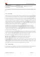
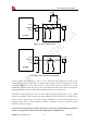
3.13.2 Reset Function
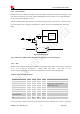
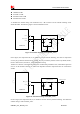
SIM5360A also have a RESET pin (PIN4) to reset the module. This function is used as an emergency reset
only when AT command “AT+CPOF” and the POWERKEY pin has no effect. User can pull the RESET
pin to ground, then the module will reset.
This pin is already pulled up in module, so the external pull-up resistor is not necessary. A 100nF capacitor
close to the RESET pin is strongly recommended. A reference circuit is recommended in the following
figure.
Treset >50ms
RESET
4.7K
47K
Reset Logic
MODULE
Reset Impulse
RESET
Figure 38: Reset circuit
Note
:
50ms<Treset<200ms. ESD components are suggested to be used on Reset pin.
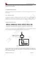
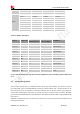
3.13.3 ADC
SIM5360A has a dedicated ADC that is available for digitizing analog signals such as battery voltage and
so on; it is on PIN 47 and PIN 46 , namely ADC1 and ADC2 . This ADC is 15 bit
successive-approximation circuit, and electronic specification is shown in the following table.
Table 29: Electronic Characteristics
Specification
Min Typ Max Unit Comments/Conditions
Resolution 15 Bits
Analog input bandwidth
–
100 –
kHz
Analog Vdd = ADC reference
2.4MHz sample rate
Gain Error -2.5 +2.5 %
Offset Error -3.5 +3.5 LSB
Input Range GND 2.2V V
Input serial resistance 2 kΩ Sample and hold switch resistance
Power supply current
Normal operation
1.5 mA
Power supply current
Off
50 200 nA
User can introduce a signal in the ADC pin directly and use the AT command “AT+CADC” to get the raw