
User's Manual

Smart Machine Smart Decision
SIM5360A_User_Manual_V1.03 2014-07-03
43
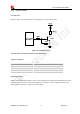
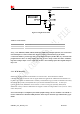
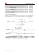
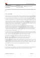
Figure 27: Flight mode switch
Table 23: Control status
GPIO4 Status Module operation
Low Level Flight Mode: RF is closed.
High Level Normal Mode: RF is working.
Note
:
1. For SIM5360, GPIO0, GPIO2, GPIO3 and GPIO5 have multiplex function, user can use them
as PCM interface to connect extend codec. Refer to section 3.11 and document [1] for details.
2. When the module is powered off, make sure all digital interfaces (PCM UART, etc) connected with
peripheral devices have no voltage higher than 0.3V. If users’ design cannot meet above conditions,
high level voltages maybe occur in GPIO pins because current leakage from above digital interfaces
may occur.
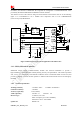
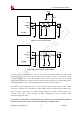
3.11 PCM Interface
SIM5360A provides hardware PCM interface for external codec. The PCM interface enables
communication with an external codec to support hands-free applications. SIM5360A PCM interface can
be used in two modes: the default mode is auxiliary PCM (8 KHz long sync mode at 128 KHz PCM CLK);
the other mode is primary PCM (8 KHz short sync mode at 2048 KHz PCM CLK). In short-sync
(primary PCM) mode, SIM5360A can be a master or a slave. In long-sync (auxiliary PCM) mode,
SIM5360A is always a master. SIM5360A also supports 3 kinds of coding formats: 8 bits (
-law or A-law)
and 16 bits (linear).
Note: PCM interface is multiplexed from GPIO (default setting). The AT command “AT+CPCM” is
used to switch between PCM and GPIO functions. Please refer to document [21] and document [1] for
details.