
User's Manual

Smart Machine Smart Decision
SIM5360A_User_Manual_V1.03 2014-07-03
42
3.10.2 Application Guide
Network status
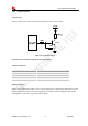
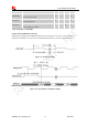
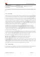
GPIO1 is used to control Network Status LED; application circuit is shown below.
Figure 26: Application circuit
Note: The value of resistor Rx depends on LED characteristic.
Table 22: LED status
LED Status Module Status
Always On Searching Network/Call Connect
200ms ON, 200ms OFF Data Transmit
800ms ON, 800ms OFF Registered network
Off
Power off / Sleep
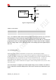
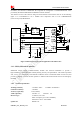
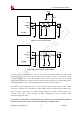
Flight mode control
GPIO4 controls SIM5360A module to enter or exit the Flight mode. In Flight mode, SIM5360A closes RF
function to prevent interference with other equipments or minimize current consumption. Bidirectional
ESD protection component is suggested to add on GPIO4.