
User's Manual

Smart Machine Smart Decision
SIM5360A_User_Manual_V1.03 2014-07-03
41
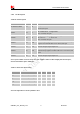
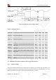
3.10.1 Pin Description
Table 20: Pin description
Note: If more GPIOs need to be used, users can configure GPIO on other multiple function interfaces,
such as PCM. Please refer to GPIO list.
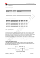
Table 21: Electronic characteristic
Symbol Parameter
Min Typ Max Unit
V
IH
High-level input voltage
1.26 1.8 2.1 V
V
IL
Low-level input voltage
-0.3 0 0.63 V
V
OH
High-level output voltage
1.35 1.8 1.8 V
V
OL
Low-level output voltage
0 0 0.45 V
Note: The output driver current of GPIOs is 2mA.
Pin name Pin No. I/O Function
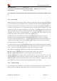
NETLIGHT/GPIO1 51 O
Output PIN as LED control for network status. If it is
unused, left open.
GPIO4 54 I
Input PIN as RF operating control.
H: Normal Mode L:Flight Mode
If it is unused, left open.
GPIO40 49 O
Output PIN as operating status indicating of module.
H: Power on L: Power off
If it is unused, left open.
GPIO41 52 I/O
General input/output PIN. It can be used as wake/interrupt
signal to host from module If it is unused, left open.
GPIO42 53 I/O General Purpose Input/Output Port.
GPIO43 50 I/O
General Purpose Input/Output Port. It can be used as
wake/interrupt signal to module from host. If it is unused, left
open.
GPIO44 48 I/O General Purpose Input/Output Port