
User's Manual

Smart Machine Smart Decision
SIM5360A_User_Manual_V1.03 2014-07-03
40
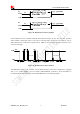
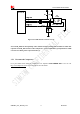
Because of high bit rate on USB bus, pay attention to influence of junction capacitance of ESD component
on USB data lines. Typically, the capacitance should be less than 4pF @1MHz.
It is recommended to use an ESD protection component such as ON SEMI (www.onsemi.com )
ESD9M5.0ST5G or ESD9L5.0ST5G.
Note
:
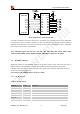
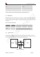
The SIM5360A has two kinds of interface (UART and USB) to connect to host CPU. USB
interface is mapped to five virtual ports: “SIMTECH HS-USB Modem 9000”, “SIMTECH HS-USB
NMEA 9000”, “SIMTECH HS-USB AT port 9000”, “SIMTECH HS-USB Diagnostics 9000” and
“SIMTECH Wireless HS-USB Ethernet Adapter 9000”.
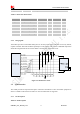
3.9 SPI Interface
SPI interface of SIM5360A is master only. It provides a duplex, synchronous, serial communication link
with peripheral devices. Its operation voltage is 1.8V, with clock rates up to 26 MHz.
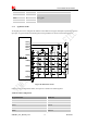
3.9.1 Pin Description
Table 18: Pin description
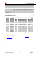
Table 19: Electronic characteristic
Symbol Parameter
Min Typ Max Unit
V
IH
High-level input voltage
1.26 1.8 2.1 V
V
IL
Low-level input voltage
-0.3 0 0.63 V
V
OH
High-level output voltage
1.35 1.8 1.8 V
V
OL
Low-level output voltage
0 0 0.45 V
3.10 GPIO Interface
SIM5360A provides a limited number of GPIO pins. All GPIOs can be configured as inputs or outputs.
User can use AT Commands to read or write GPIOs status. Refer to ATC document for details.
Pin name Pin No. Function
SPI_CS 9
SPI chip-select; not mandatory in a point-to-point connection
SPI_MISO 7
SPI master in/slave out data
SPI_CLK 6
SPI clock
SPI_MOSI 8
SPI master out/slave in data