
User's Manual

Smart Machine Smart Decision
SIM5360A_User_Manual_V1.03 2014-07-03
38
KBC4 36
KBR0 30
Driving pads
KBR1 29
KBR2 30
KBR3 35
KBR4 34
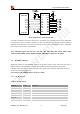
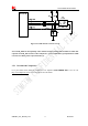
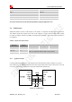
3.7.2 Application Guide
All keypad pins can be configured for GPIOs. These GPIOs also support interruption operation if used as
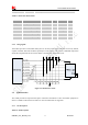
input pins. A typical circuit about the keypad (5*5 keypad matrix) is shown in the following figure.
KBR4
KBR3
KBR2
KBR1
KBR0
KBC0
KBC1
KBC2
KBC3
KBC4
Figure 24: Reference circuit
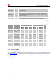
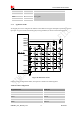
If these pins are configured for GPIOs, the sequence is listed in the following table.
Table 16: GPIO configuration
Keypad interface GPIO No.
KBR4 GPIO6
KBR3 GPIO7
KBR2 GPIO8
KBR1 GPIO9
KBR0 GPIO10