
User's Manual

Smart Machine Smart Decision
SIM5360A_User_Manual_V1.03 2014-07-03
34
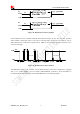
Table 13: Electronic characteristic
Symbol Parameter
3.0V mode 1.8V mode
Unit
Min Typ Max Min
Ty
p
Max
USIM_VD
D
LDO power
output
2.71 2.85 3.05
1.7 1.8 1.9
V
V
IH
High-level
input voltage
0.65·USI
M_VDD
-
USIM_V
DD +0.3
0.65·USI
M_VDD
-
USIM_V
DD +0.3
V
V
IL
Low-level
input voltage
-0.3 0
0.3·USI
M_VDD
-0.3 0
0.3·USI
M_VDD
V
V
OH
High-level
output voltage
2.71 2.85 3.05
1.7 1.8 1.9
V
V
OL
Low-level
output voltage
0 0 0.45 0 0 0.45 V
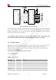
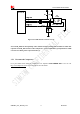
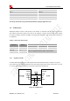
3.5.2 Application Guide
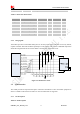
It is recommended to use an ESD protection component such as ST (www.st.com ) ESDA6V1W5 or ON
SEMI (www.onsemi.com ) SMF05C. Note that the SIM peripheral circuit should be close to the SIM card
socket. The reference circuit of the 6-pin SIM card holder is illustrated in the following figure.
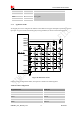
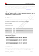
Pin name Pin Description
USIM_CLK 19 USIM Card Clock
USIM_RST 18 USIM Card Reset
USIM_DATA 17
USIM Card data I/O, which has been pulled up with a 22kR resistor to
USIM_VDD in module. Do not pull up or pull down in users’
application circuit.
USIM_VDD 20
USIM Card Power output depends automatically on USIM mode,one
is 3.0V±10%, another is 1.8V±10%. Current is less than 50mA.